Video: Programming for Additive Turning of Cylindrical Parts
Directed energy deposition while the part is spinning enables a means of 3D printing axially symmetric parts. The operation is like CNC turning with material added instead of machined. Open Mind discusses programming the machine paths for this type of build.
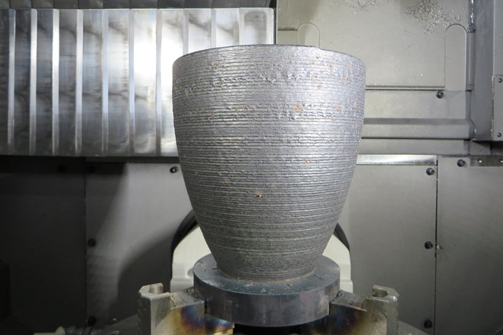
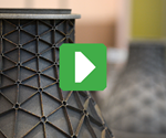
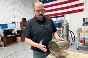
DED as the work rotates can produce a part such as this. The video below illustrates programming and describes why five-axis motion is important. Photo credit: Open Mind Technologies
Applying directed energy deposition (DED) to a part that is rotating allows for a means of metal 3D printing that is essentially the opposite of turning in CNC machining. Rather than removing metal in a cylindrical or axially symmetrical pattern, which is what turning does, this “additive turning” adds material in the same fashion. This is additive manufacturing (AM) for building parts such as large cylindrical housings, potentially as an alternative to casting this type of part.
In this video, David Bourdages, product manager with computer-aided manufacturing software provider Open Mind Technologies, demonstrates programming for this type of AM build. Open Mind’s programming technology has long been used for CNC machining, and the company has adapted its programming into now also creating toolpaths for DED. Bourdages illustrates the important role five-axis machine motion plays in additive turning (as well as in DED in general), and also talks about the validation of additive-turned components recently performed by Oak Ridge National Laboratory.
Resources
Transcript
Peter Zelinski, Additive Manufacturing
Directed energy deposition, or DED, is a form of metal additive manufacturing that follows a toolpath like a CNC machine tool — sort of. There's no tool; there’s a nozzle depositing metal, but the machine moves the nozzle through XYZ space in a path that's programmed like a machine tool. Hello, I'm Pete Zelinski with additivemanufacturing.media. This video is part of our occasional series on the role of software in advancing additive manufacturing.
My guest is David Bourdages, product manager with Open Mind. Open Mind is the developer of HyperMill software for programming metal cutting machine tools, CAM software and now a version of the software for programming the moves of metal deposition. One really interesting possibility here is additive turning, spinning the part and 3D printing a cylindrical form as it spins. So, David, to start, can you talk about the challenges of programming DED in general? How is this like programming CNC machining? Where is the metal cut? And how is it different?
David Bourdages, Open Mind
One thing that we have to be careful about is that we have to keep the nozzle more or less vertical when building certain kinds of parts. And because here we're talking about liquid melt pool compared to a tool to a milling tool. Also another point which is really important is that when adding the material on an existing part or casting, the additive device should stay normal to the base surface to ensure a proper deposition. Also, we should consider the deposition speed and the speed at which the bead will move on the part.
Peter Zelinski
What I'd like to ask you to do now is share your screen. And in the span of just a couple minutes, give us a look at what it's like to program DED, and in fact, maybe show us additive turning: programming DED for an axially symmetric part.
David Bourdages
Yeah, I prepared two small examples to show you how it works, because it's fairly simple to program this. The way that we're working inside HyperMill, we broke this into separate processes. So we have the definition of what we call a reference job, and then we are applying an additive manufacturing job over this. The first part of this is what we call the three-axis simultaneous finishing, which is mainly a turning cycle that we're using for this.
Here, you will see this is the part that we would like to build: in this case, a rotational part. We would build, in this case, only one bead thickness — one B thickness. Therefore, I will just show you: here we have the contour profile of the part itself, which you can see it this way. And then we are selecting this path here. Sorry, here is my user interface. So we are selecting this contour here. And we are selecting this synchronization line to guide the tool vector. What will happen when calculating this, is that we have a motion, which is looking like this here. I will just move in this view, because this is the easiest way to understand how this will work. As you can see here, the tool will move along the path. And then thanks to the vector that we gave, we are interpolating between these vectors along the time that we are moving in the space. This is important because when we are building something like this in additive, it's always important to point toward the previous path or the previous part, which has been already built therefore the motion will look like this. But this simply a 2D approach, a 2D view of what will happen later on.
Then, once we have this reference job, we are using it in the additive manufacturing job. And what the additive manufacturing job will do is — thanks to some parameters that we're giving to the software — it will use this and generate a five-axis path, which is following the geometry turning around the part and then generating the tool vector all around, because most of the additive processes of the machine are not offering the turning process itself. So, you need to go through a five-axis process to do it. And this is how we are doing this.
Therefore, as you can see here, there is a bunch of vectors, it would be really hard to analyze this. But since we are starting with really a simple 2D process, then it's easy to analyze what will go on with the tool vector and then to go to the five-axis.
If you accept, I will go to another example, which is showing the strength of the additive turning process, which is where it becomes really interesting, because if you take a part like this one here, what you see here, we have a variable wall thickness. And this is where it becomes really interesting. So there you can generate a path which is looking something like this one here. Follow this path, and when I play in exactly the same logic here, I've got some vectors to guide the tool orientation also, and if we are taking a look to what it is looking like, we will have something like this.
So what will happen is along the path here where we have only a single bead, so a single thickness of wall, this is quite similar to the previous one. But where it becomes really interesting is that when we are coming in the thicker part, you can imagine that what we need to do here is that we will need to move kind of in a “zig-zag” motion, but then also to make sure that we are always pointing to what was already built. And this is where it's really strong, because then you can really have any type of rotational shape with different thickness, and the nozzle will always point the right direction in order to be able to build this.
Peter Zelinski
You're making it clear how vital five-axis motion capability is for the additive turning.
David Bourdages
In fact, it's more than only for the additive turning. This is more about additive turning, what we are speaking about here, but in the majority of the cases that I have seen, it's almost always five-axis motion that we have to apply. Because, think to anytime you had to repair something, it's really rare except for the demo part. So where they are building a simple block on a flat stock — usually you need to repair an edge, you need to do something about a 3D shape or something like this — you will always be in five-axis.
Peter Zelinski
How far have you gotten with this mode of additive? Are there are there any potential parts or applications in which additive turning seems to offer a really promising way to generate the form that's needed?
David Bourdages
In fact, the project itself started with a customer request — as many projects are starting. So the customer wanted to move from a manufacturing process with sheet metal. So they had some sheet metal, made a special alloy, they had to roll this, weld this together, grinding, polishing and all this — and you understand there was quite a lot of manual work, it was very time consuming. And, in fact, it has a really long lead time.
So they turned to the additive manufacturing process to replace their existing process. And so they started with a lead time for this sheet metal process of about four months to a lead time of a couple of weeks to do the same part. And here, we are speaking about fairly large parts: about a meter, meter-and-a-half — so, three to four or five feet in diameter. In addition, now, they are able to build the part with variable wall thickness and add other features such as flange, outside or inside the bar.
Peter Zelinski
Have you been able to demonstrate the reliability of these parts? Have you proven the part that’s made this way is solid?
David Bourdages
In fact, we are working closely with the Oak Ridge National Lab to test different approaches not only in the additive turning, but additive turning was tested also there. And recently they scanned the part and then they built using the additive turning on a Mazak hotwire layer machine, and they were really astonished about the quality of the build. So in the testing part, they achieved a porosity of 0.01 percent, so which is really not much. And in the past, the lowest porosity they achieved before was 0.06 percent. So it's, it's a factor of six. So it's really something good.
My assumption is that this is due to the fact that we're building in the best condition. So we are staying normal to the shape, there is no start and stop — which is something really critical when we are speaking about porosity — and also it’s a continuous and smooth motion.
Peter Zelinski
All right. Let's leave it at that. Programming technology developed and proven for machining now advancing and extending the capabilities of metal 3D printing. David, thank you for joining me.
David Bourdages
Thank you very much for your invitation. I appreciate it.
Peter Zelinski
I’m Pete Zelinski. Learn much more about the technology of additive manufacturing for industrial production at additivemanufacturing.media.
Related Content
New Zeda Additive Manufacturing Factory in Ohio Will Serve Medical, Military and Aerospace Production
Site providing laser powder bed fusion as well as machining and other postprocessing will open in late 2023, and will employ over 100. Chief technology officer Greg Morris sees economic and personnel advantages of serving different markets from a single AM facility.
Read MoreHow Machining Makes AM Successful for Innovative 3D Manufacturing
Connections between metal 3D printing and CNC machining serve the Indiana manufacturer in many ways. One connection is customer conversations that resemble a machining job shop. Here is a look at a small company that has advanced quickly to become a thriving additive manufacturing part producer.
Read MoreVulcanForms Is Forging a New Model for Large-Scale Production (and It's More Than 3D Printing)
The MIT spinout leverages proprietary high-power laser powder bed fusion alongside machining in the context of digitized, cost-effective and “maniacally focused” production.
Read MoreVideo: For 3D Printed Aircraft Structure, Machining Aids Fatigue Strength
Machining is a valuable complement to directed energy deposition, says Big Metal Additive. Topology-optimized aircraft parts illustrate the improvement in part performance from machining as the part is being built.
Read MoreRead Next
Video: What is Directed Energy Deposition?
DED is an additive manufacturing process that builds features or parts in metal by placing material where needed.
Read MoreDirecting the Future of Laser Metal Deposition (LMD)
Formalloy is proving that LMD is for more than repairs and large parts. Fast deposition rates, fine detail capabilities and multimaterial support promise to change how parts are designed and made.
Read MoreAdditive Manufacturing for Large Parts
Powder-bed fusion is driving the hype for additive manufacturing right now, but it may not be the best answer. Directed energy deposition is a strong contender.
Read More

