Additive Technology Delivers Small Satellites to Space
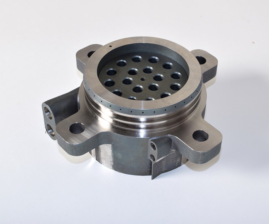
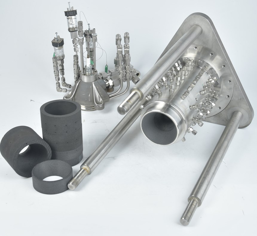
Researchers at the German Aerospace Center (DLR) have developed a reusable rocket engine specifically for the launch of small satellites. The complex injector heads are 3D printed which unlocks additional performance, reduces the parts count, speeds up production time, and reduces weight and costs.
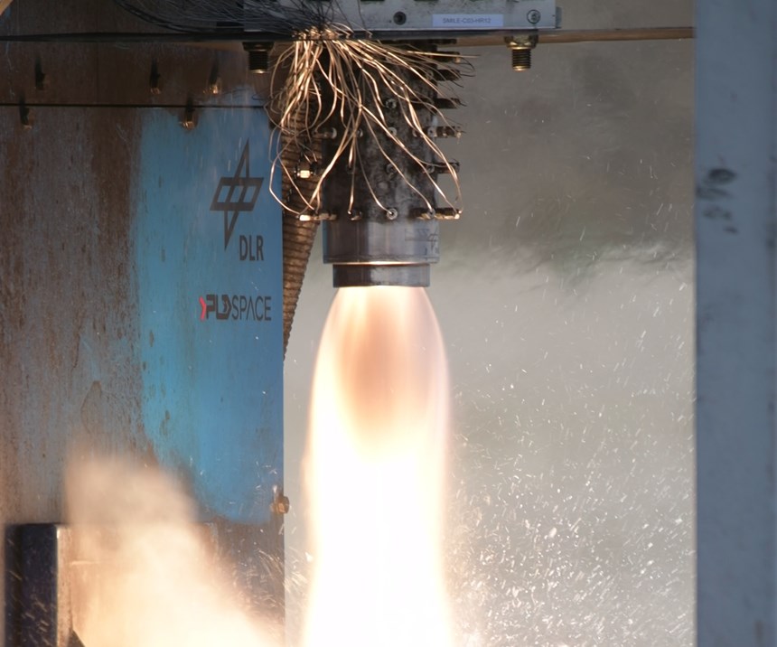
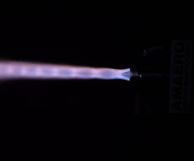
When Elon Musk showed off videos of a SpaceX test firing of a flight-ready Raptor engine in February 2019, he tweeted that he was “so proud of the great work” by the SpaceX team. This is probably how the researchers at the German Aerospace Center (DLR) and their project partner 3D Systems felt when the liquid oxygen and kerosene mixed in their rocket engine in initial hot firing tests in October 2018.
The reusable rocket engine was developed as part of the EU project SMILE (Small Innovative Launcher for Europe), which aims to design a small satellite launch vehicle to deliver small satellites (weighing less than 70 kg) into near-Earth orbits. The German Aerospace Center is one of 14 participating organizations* and is responsible for developing a liquid rocket engine injector for the SMILE Project launcher.
“Traditionally, small satellites have tended to be carried into space as piggyback payloads on rockets commissioned for larger spacecraft,” explains Markus Kuhn from the DLR, Institute of Structures and Design in Stuttgart, Germany. “In this situation the primary payload takes priority, and extra payloads have to be adapted to the launch schedule and orbit. Therefore, many companies and research institutes are currently developing micro-launchers for small-satellite deliveries, but so far attempts to create reliable and affordable micro-launchers have failed, mainly due to high launch prices or immature technology.”
In order to offer a more cost-efficient solution for small satellite launchers, the Institute focuses on the technology required for the liquid propulsion system of the rocket engine (which is the most expensive part), onboard electronics and cost-effective production. According to Kuhn, the injector head is one of the key components of a liquid rocket engine, but since it integrates numerous piece parts which are manufactured to tight tolerances and inspected meticulously after every manufacturing step, production takes a long time and is very expensive. Moreover, the casting process traditionally used limits the minimum wall thickness of the components, which prevents lightweight designs.
Monolithic Design Reduces Lead Times
When project partner 3D Systems suggested using its laser beam melting technology to produce the coaxial injector head, the researchers at the DLR were immediately interested because the advantages offered by additive manufacturing (AM) are obvious: Optimized design capabilities with 3D printing allow for a reduction of mass and an improvement of the injector's performance. A reduction in individual piece parts, manufacturing and assembly steps allows for a significant reduction in manufacturing cost and lead time of the engines.
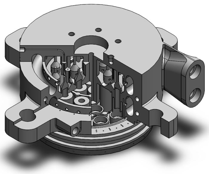
“Our original design included 30 parts with many different interfaces to be machined and welded together,” Kuhn says. “Reducing the necessary components from 30 to one contributed to a final weight reduction of 10 percent and removed known points of failure at fastening sites to alleviate related quality control measures and improve system performance.”
Integrating Complex Cooling Channels
Moreover, the design of a printed injector added new possibilities for fuel and coolant distribution, which not only enhances part performance but extends the part life span.
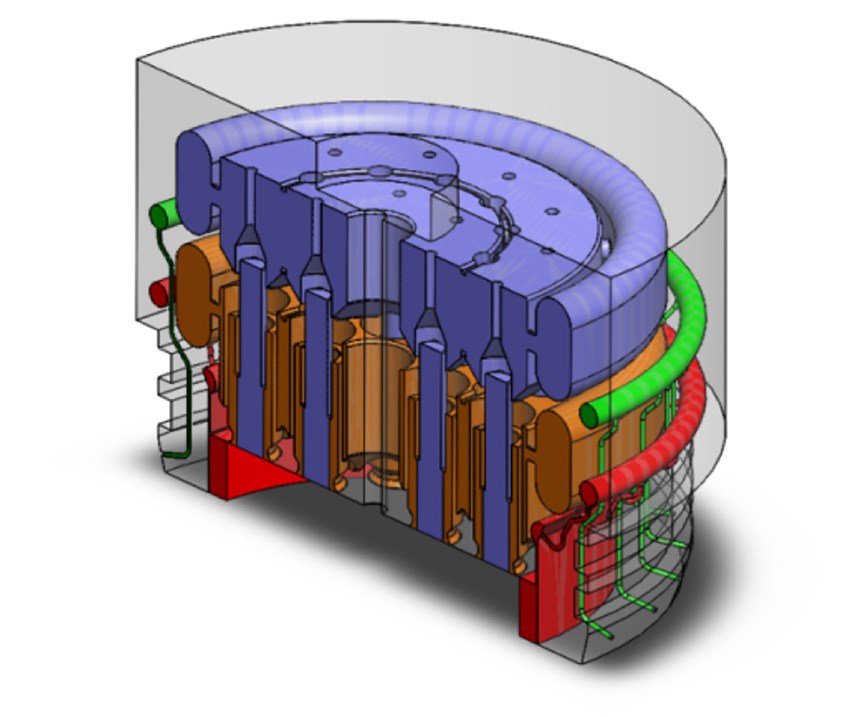
Directly integrating a coolant distribution system with the injector allows engineers to implement and independently control wall transpiration and film cooling techniques. When applied within the injector, a coolant film forms on the hot inner side of the combustion chamber that protects the wall structure from high heat fluxes. According to Kuhn, this type of system is much easier and cheaper to manufacture than traditional regenerative cooling.
Together with sophisticated ceramic materials like ceramic fiber-matrix composites (CMCs), the design and manufacturing approach developed by DLR and 3D Systems could potentially enable the structures and systems developed for the injector head to be reused multiple times, which was one of the SMILE project’s objectives.
The cooling solution consist of fine channels with minimum feature sizes of 0.2 mm and maximum length/diameter ratios of 45. Since these fine and complex internal channels and cavities cannot be postprocessed easily, a layer thickness of 30 microns was chosen for the production of the injector to achieve the required surface quality. The additive approach to the propellant channel design also allows an easy implementation of pressure and temperature sensor channels.
Co-Engineering Design for Manufacturing
However, several technical issues and AM parameters need to be controlled in order to provide a robust and reliable injector design which reduces engine cost, but not engine reliability, explains Koen Huybrechts, project engineer for 3D Systems in Leuven, Belgium. “For many designers, the description or visualization of pure required functionalities versus design impressions originating from well-known, mature manufacturing techniques is a difficult distinction to make,” he explains. “In the design process for the injector, the technical design was done by the DLR, while the design-for-manufacturing aspects were integrated and optimized by our application engineers in our Customer Innovation Center in Belgium. This co-engineering approach boosted the iterative approach in which step-by-step, the overall added-value of the injector within the complete propulsion system increased.”
For Kuhn it was absolutely essential to work with 3D Systems, because the expertise at the DLR lies in the development of high-temperature composite materials with polymer and ceramic matrix in innovative, high-performance structures, not in additive manufacturing. He says that he appreciated the bundled knowledge found at 3D Systems’ Innovation Center, which serves different parties and industries and where experienced staff get their minds challenged by a diverse range of customers, who get “advice from a realistic point of view.”
“Designers are used to using design libraries in conventional machining,” Huybrechts says. “But in AM you can read as many books as you like, it is experience what counts. Our designers and engineers have so many parameters in their head to optimally design a part, knowledge that cannot be found in manuals or books.”
One important parameter he cites is the orientation in which a part is printed.
Considering Part Orientation in Design for AM
Knowing the main functional requirements with their dimensions and volumetric design space, the most important decision—at the earliest stage possible—is to determine the orientation in which a part is printed. The layer-by-layer process inherently means that not all geometries can be printed in any orientation, and that part orientation has a strong influence on many quality characteristics. Some design tips are listed below:
The most important decision—at the earliest stage possible—is to determine the orientation in which a part is printed.
The orientation in which a part is printed influences roughness. A well-known property is the so-called staircasing effect, which strongly depends on the layer thickness used to manufacture a part.
Staircasing is a phenomenon associated with 3D printing when the layer marks become distinctly visible on the surface of the parts, giving the perception of a staircase, Huybrechts explains. “To achieve the required surface quality for the injector head, we chose a layer thickness of 30 microns and tried to orient the part as vertical as possible in the build chamber, because layer marks are prevalent on curved and angled surfaces. Since layers are sliced and deposited with respect to the vertical axis, any change in the nature of the part geometry with respect to this axis will result in a staircasing effect.”
The smallest and/or most complex elements determine the orientation. In the case of the injector, it is the 0.2-mm cooling film gap (the axis of the cylinder) that imposes a vertical orientation, Huybrechts explains. “This reduced the amount of potential orientations to two during the design phase.”
Consider powder evacuation for any internal cavities. The removal of powder out of all internal cavities—together with a firm connection to the baseplate—finalized the orientation with all exit holes pointing upwards. “For the injector, special attention was given to the challenging task of removing all remaining powder out of the internal cavities and channels,” he says. “A weight of almost 30 kg, baseplate included, is difficult to handle manually. It is however essential to remove all powder in this phase since—once the part had its heat treatment—any remaining powder does not flow anymore.”
Avoid support structures where a controlled removal strategy would be impossible to implement. A next challenge was to avoid the need for any support structure in cavities where a controlled method to remove support structures afterwards would be impossible to implement. Mainly for the cavities where oxidizer and fuel are mixed, a dome-shaped redesign drastically reshaped the internal layout, requiring a new CFD validation.
Keep horizontal channels to a limited radius. Huybrechts explains that the large inlet channels are printed with their axes parallel to the horizontal plane. “A rule of thumb is that horizontal channels can be printed without the need for support if the radius remains below 4 mm,” he says. “Although the channels were designed with a circular cross-section exceeding this maximum size, the functionality only handles about a certain mass flow. The result was to reshape circular channels to an oval cross-section, guaranteeing the performance of the injector.”
From Design to Prototype
After the most beneficial part orientation was selected, the design was optimized for functionality and manufacturability at the same time in an iterative procedure. 3D Systems performed pre-printing operations to facilitate powder removal in postprocessing, as well as a printability check to ensure the part would build without complication. Once printed, 3D Systems’ team removed unused material from the part’s interior, heat-treated the part for stress relief, and removed the part from the build plate using wire dlectrical discharge machining (EDM).
Other postprocessing steps include micro shot peening, machining (milling and turning), ultrasonic cleaning and final quality control. The team designed and produced six different versions of the injector head over the course of the three-year project and a partial proof-of-concept was printed at 3D Systems’ Leuven CIC on a 3D Systems ProX DMP 320 metal printer in LaserForm Ni718 (A), an oxidation- and corrosion-resistant Inconel alloy.
Hot firing tests confirmed a good performance of the first prototype.
Drivers for Additive Manufacturing
In general, 3D printing adds new possibilities for fuel and coolant distribution and supports optimizing for performance and cooling in fuel injectors. Thermal, mass and hydraulic performances can all be independently optimized and are no longer contingent on the selected fabrication methods.
In the case of the liquid rocket engine injector developed by DLR, 3D printing offered improvements in quality over conventional production techniques, such as 3D-printed propellant channels that allowed for the easy implementation of pressure and sensor channels. The final injector is a highly integrated and multifunctional part that avoids a substantial number of production and assembly steps.
A short lead time of approximately four weeks made it possible to test more parts compared to other production processes, leading to a larger testing database and reduced development time.
* The SMILE consortium consists of 14 partners: NLR – Netherlands Aerospace Centre as coordinator (Netherlands), 3D Systems (Belgium), Airborne Composites Automation (Netherlands), Andøya Space Centre (Norway), BoesAdvies (Netherlands), DLR – German Aerospace Centre (Germany), Heron Engineering (Greece), ISIS – Innovative Solutions in Space (Netherlands), Nammo Raufoss AS (Norway), INCAS – National Institute for Aerospace Research (Romania), PLD Space (Spain), Tecnalia (Spain), Terma (Denmark) und WEPA Technologies (Germany). This project has received funding from the European Union’s “Horizon 2020 research and innovation program” under grant agreement No. 687242.
Related Content
Sustainable Furniture Company Model No. Maintains Product Focus with Switch from DIY to Industrial 3D Printers
The startup founded in 2018 has matured in its product offerings as well as its manufacturing equipment, moving from homegrown 3D printers to industrial large-format machines.
Read MoreGE Additive Helps Build Large Metal 3D Printed Aerospace Part
The research is part of an initiative to develop more fuel-efficient air transport technologies as well as a strong, globally competitive aeronautical industry supply chain in Europe.
Read MoreNext-Gen Horse Trailers to Be Built With Robotic 3D Printing
Double D Trailers is currently developing a prototype horse trailer that will be made with large-format additive manufacturing. The technology brings potential benefits for labor, weight and design features to this subset of recreational vehicles.
Read MoreMultimodal Powders Bring Uniform Layers, Downstream Benefits for Metal Additive Manufacturing
A blend of particle sizes is the key to Uniformity Labs’ powders for 3D printing. The multimodal materials make greater use of the output from gas atomization while bringing productivity advantages to laser powder bed fusion and, increasingly, binder jetting.
Read MoreRead Next
Video: How Additive Manufacturing Is Advancing the Space Industry
By making launch vehicles more efficient and easier to manufacture, AM lets small companies play a significant role in space. Here is a conversation with an aspiring startup.
Read MoreAM Design May (Finally) Launch the Aerospike Engine
A team of engineers turns to additive design to create—and successfully test—“the holy grail of the spaceship movement.”
Read MoreProfilometry-Based Indentation Plastometry (PIP) as an Alternative to Standard Tensile Testing
UK-based Plastometrex offers a benchtop testing device utilizing PIP to quickly and easily analyze the yield strength, tensile strength and uniform elongation of samples and even printed parts. The solution is particularly useful for additive manufacturing.
Read More

