Tensile testing is a standard means of determining material properties, but could it be made more efficient, faster and even nondestructive?
A method of material testing from UK-based Plastometrex is already making this possible. Developed by a team of former University of Cambridge materials scientists, including Dr. Jimmy Campbell, chief technology officer, Profilometry-based Indentation Plastometry or PIP provides a means of determining multiple material characteristics with a test that requires only a small indent to the sample or even a part itself.
Profilometry-based indentation plastometry or PIP is a nondestructive method for determining tensile strength. Rather than destructive testing of witness coupons, the process requires only a small indentation to be made in a sample (which can be as small as 3 × 3 × 1.5 mm) or even on the part itself. Source: Plastometrex
Challenges with Standard Tensile Testing
Typical tensile testing requires that samples be manufactured in a particular size and shape, which are then destroyed by the test. PIP offers a nondestructive alternative. Source: Plastometrex
The typical way of capturing yield and tensile strength involves producing dog bone-shaped samples (in additive manufacturing, they might be 3D printed directly in this geometry or cut from a larger piece of material) which are then pulled mechanically until they yield and break. The method is effective, broadly used and widely accepted; however, it also introduces challenges that can be particular barriers to additive.
For example, additively manufactured metal parts can have different properties depending on their location within the build envelope, and may even exhibit different material behavior across their geometry. Capturing representative samples from each distinct area of a build or part can be difficult or even impossible if these regions don’t offer enough material to produce a standard tensile specimen.
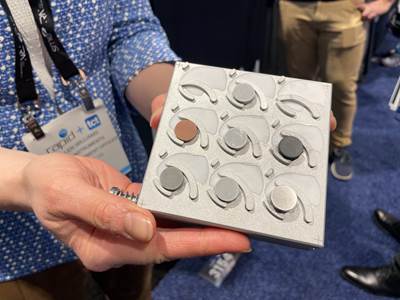
The indentations left behind by PIP testing are visible on the material’s surface, but small enough that they could be removed with postprocessing and finishing operations in cases where the part itself might be tested rather than a sample like this. Source: Plastometrex
The size of these specimens is also a challenge in AM, where limiting the amount of material used is often the goal. Printing in excess to produce tensile samples extends build times and also means using more material — perhaps not a major concern when printing with something like standard 316L stainless steel, but a factor that can significantly add to costs when dealing with an expensive alloy.
“Standard tensile yield tests require quite a bit of material,” Campbell says, referring to the standard 115-millimeter dog bone sample. “Even if you print to near-net shape, the sample will still often require CNC machining. This introduces delays in the process. We’ve surveyed over 1,000 companies and found that the average turnaround time is around five days for tensile testing — but could be as long as months.”
How PIP Works
While not developed specifically for additive manufacturing, Plastometrex’s Profilometry-based Indentation Plastometry testing method helps to avoid these challenges, requiring only a small sample of material which is easier to print or extract from a 3D printed geometry. PIP is based on indentation plastometry, a test method that can identify multiple material properties from a simple indentation operation.
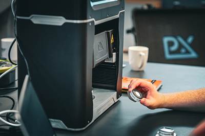
The PLX-Benchtop machine is small enough to sit on a tabletop and makes it possible to conduct a tensile test in about 15 minutes. A “hot stage” that heats samples up to 800°C can be added as an option for testing material that must operate at high temperatures. Source: Plastometrex
Using the company’s PLX-Benchtop or PLX-Portable machine, a user can load a sample as small as 3 × 3 × 1.5 mm onto the test platform. These samples can be separate coupons included in a build, or overprint areas cut from the part, or even the part itself; the indents left are small enough they can typically be addressed in the normal course of postprocessing.
A spherical indenter (similar to that used in hardness testing) descends and makes a small indent in the sample or part. (Two indenter sizes are offered — a 0.5-mm radius option that makes an indentation about 100 microns deep and 0.5 mm across, and a larger one that doubles the depth and width. The scale itself is significant; compared to nanoindentation used in some academic settings, the size of the indents used in PIP are large enough to be considered measures of the bulk material properties.) Then, the indentation and surrounding area are scanned with a profilometer to determine the full profile shape of the indent.
The experimental result is compared against a computer model until a good match is achieved. The model contains data for materials ranging from soft copper through tool steel; it predicts the shape of the indent for a given set of properties and then, based on the experimental profilometry scan, modifies the material properties within its model until there is good agreement between the experimental and modeled data. This enables the determination of the material’s yield strength, tensile strength and uniform elongation.
Plastometrex’s Corsica software analyzes scan data to arrive at the yield stress, ultimate tensile strength and uniform elongation for the sample. Because PIP is based on technology used in hardness testing, this information can be obtained at the same time as well.
Source: Plastometrex
Testing can be done in less than 5 minutes, Campbell says. Preparing the samples involves just a small bit of surface grinding; from start to finish, the entire process can be completed in just about 15 minutes.
Use Cases for Profilometry-Based Indentation Plastometry
Despite the broader use cases for the PIP process, Plastometrex has found that this technique is particularly well-suited to addressing material property questions in additive manufacturing. Around 50% of the PLX machines sold are being used for AM development, research or production, Campbell says.
“We’re metal agnostic,” Campbell says. “If it’s metallic, we can test it.”

Plastometrex analyzed three different regions of this 3D printed, topology optimized bracket, along with a witness coupon. The PIP test revealed that there could be up to a 20% variation in mechanical properties across the different regions of the part compared to the standard coupon test. Source: Plastometrex
PIP is already providing insights for additive manufacturing. In a project with Gestamp, a topology optimized bracket was analyzed in multiple locations using Plastometrex’s method, revealing variation in its properties as a function of location — variation not captured with a standard dog bone tensile test.
“I think all additive manufacturers are aware that this is an issue,” Campbell says, “but until now there hasn’t been an easy way to test it.”
In another project completed with collaborator machine provider Renishaw, PIP was used to analyze 3D printed nickel superalloy parts after they underwent heat treatment. The project revealed that the parts had different yield strength depending on whether they were near the front or back of the oven; on closer inspection the team discovered that the gas flow in the furnace was cooling some parts prematurely and affecting their material properties, a problem that was then resolved.
Plastometrex sees PIP being used today for material development, parameter optimization, design optimization and failure analysis. What’s next for the technology with regard to additive manufacturing is getting into quality control as an accepted method. The company is currently working with ASTM and ISO to establish a standard covering PIP as a viable testing method alongside or as a replacement to standard tensile testing.
“Getting that standard in place will lower the barrier to entry,” Campbell says. “Rather than each customer establishing their own processes internally, they can deploy this in line with the standard.”
Related Content
Zeiss Hosts Digital Event for Metrology and Software April 15-19
The event is designed to offer a unique opportunity to gain new, interesting insights and exchange ideas with industry experts from all over the world.
Read MoreVideo: Scanning for Fast Model Capture and Validation of AM Parts
3D printing offers a fast way to obtain a part. Can developing the printable file and validating the printed part be done rapidly as well? See fast measurement technology for complex 3D forms I found at IMTS.
Read MoreMedical Molder Relies on 3D Printing to Speed Development of Inspection Fixtures
Medical molder Medbio uses FFF and SLA 3D printers in designing (and sometimes producing) its inspection fixtures.
Read MoreRenishaw and Plastometrex Collaborate to Increase Precision, Efficiency of AM Mechanical Property Analysis
Plastometrex’s PLX-Benchtop facilitates rapid, direct testing on different sections of additively manufactured parts, delivering comprehensive stress-strain curves in minutes to provide a more precise evaluation of a part’s mechanical properties.
Read MoreRead Next
User-Friendly Mass Spectrometry Tool to Enable AM
The Massbox is a technology designed to simplify mass spectrometry by bypassing the need to send samples to the lab for characterization and testing purposes. Exum Instruments’ debut tool is suitable for AM as it can assist with quality assurance, material characterization and failure analysis.
Read MoreRenishaw and Plastometrex Collaborate to Increase Precision, Efficiency of AM Mechanical Property Analysis
Plastometrex’s PLX-Benchtop facilitates rapid, direct testing on different sections of additively manufactured parts, delivering comprehensive stress-strain curves in minutes to provide a more precise evaluation of a part’s mechanical properties.
Read MoreCrushable Lattices: The Lightweight Structures That Will Protect an Interplanetary Payload
NASA uses laser powder bed fusion plus chemical etching to create the lattice forms engineered to keep Mars rocks safe during a crash landing on Earth.
Read More

.jpg;width=70;height=70;mode=crop)

