Video: The STL File Can Produce Surface Defects in 3D-Printed Parts
Timothy Simpson of Penn State University discusses the influence of model definition in additive manufacturing and what to do about its effects.
The way a model is defined for additive manufacturing (AM) can affect the outcome of the 3D printing build. Here, Professor Timothy Simpson of Penn State University discusses the influence of STL-based model definition and what to do about its effects.
A co-director of the Center for Innovative Materials Processing Through Direct Digital Deposition (CIMP-3D) at Penn State, Dr. Simpson is a regular contributor to our site. He is also part of the faculty of a graduate-level program in AM.
Transcript
Peter Zelinski, Additive Manufacturing
I'm Pete Zelinski with Additive Manufacturing magazine. I am here with Dr. Tim Simpson, co-director of the Center for Innovative Materials Processing Through Direct Digital Deposition (CIMP-3D) at Penn State University. So Tim, you've got an additive manufactured part with you. We understand that a 3D printed metal part is usually a machined part, there are potentially defects in the surface [or] witness marks like 3D printing layer lines. But there is another phenomenon that could affect the surface quality and the form to an even greater extent. And that has to do with the way the model is defined for additive manufacturing. So, talk about that.
Tim Simpson, PSU
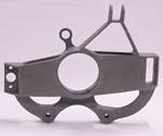
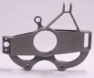
Absolutely. So this is actually an upgrade for the suspension on the formula racecar team here at Penn State. Vincent Miranda was an undergrad working with my colleague Todd Palmer to design and optimize this and eventually you want to print a functional component and put it on the car. Like most 3D printed models, he started in a CAD program, develop your solid model, and then you export an STL file that then you read into your build preparation software: Magics or Netfabb, something along those lines.
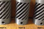
The problem is, after you've finished creating your solid model in your CAD program and exporting it into an STL file, you approximate your perfect geometry, which are a bunch of little lines or triangles, that then gets read into your build preparation software. Those approximations and triangles can actually lead to a unique feature as well, as you can see on the surface here. This is the result of, not the layering that goes on, but actually a series of small lines and triangles used to approximate a perfect circle that you've already designed in your CAD package.
Peter Zelinski
I do see that. I see the straight-line facets on the curve of the part here and more significantly on the ID of this bore. Is the part usable this way?
Tim Simpson
Actually no. Think about if you've got a shaft or a bearing rotating inside here, and now it's clunking along instead of [having] a nice smooth surface. So you definitely need to, again, common misconception, hey, If I print it I'm done. But no, we really need to think about how are we going to machine this, adding machining allowances, what are the critical interfaces that are meeting surfaces and those sorts of things. You definitely want to [keep] those considerations in mind when you're creating your geometry and printing your part.
Peter Zelinski
I wanted this bore to be round and it comes out not round, it's made up of little line segments. What do I do about that?
Tim Simpson
A couple of options for you. One is to approximate it with more and more smaller and smaller lines and smaller and smaller triangles. Your file is going to blow really, really big because now you've got a bunch of triangles to approximate that and those little triangles, certainly making sure all the corners meet up and everything you could have errors in your STL file.
The other idea is that some 3D printing companies are actually creating software that pairs with their 3D printer, so that you actually take your CAD file directly and slice it up and print it. 3D Systems for instance, with their 3DExpert, they use direct metal printing, where you go directly from your native CAD so your perfect circles are sliced, then sent to the printer to print. There are others working on that type of capability as well.
Then finally, you can think about well, I know I'm going to have to machine it. So let's actually make sure we add enough machining allowances on there or depending on the the orientation of the part as you're building it. There may be support structures in here. So let's actually design machining guides to help align the tool, or let's create features to help hold our datums to create references that then make it easier to machine, to bore out interfaces or flattened critical interfaces in your part.
Related Content
The New Misperceptions Of AM: AM Radio #35
Tim Simpson and Peter Zelinski discuss a way additive manufacturing has advanced: The misperceptions have shifted. Knowledge of AM among manufacturers is more sophisticated now. The concerns that inform the perceptions of newcomers have therefore changed.
Read More3MF File Format for Additive Manufacturing: More Than Geometry
The file format offers a less data-intensive way of recording part geometry, as well as details about build preparation, material, process and more.
Read More8 Cool Parts From Formnext 2023: The Cool Parts Show #65
New additive manufacturing technologies on display at Formnext were in many cases producing notable end-use components. Here are some of the coolest parts we found at this year’s show.
Read MoreHow to Organize for Additive Production: AM Radio #42
Tim Simpson and Peter Zelinski discuss the next steps for succeeding with AM: After technical and process successes come the cultural, organizational and even costing considerations associated with this mode of manufacturing.
Read MoreRead Next
3D Printing Resolution: High or Low?
When does it make sense to opt for a high- or low-resolution print? An example from Creat3D illustrates the difference.
Read MoreUnderstanding the As-Printed Surface of a Metal 3D Printed Part
The model definition for additive manufacturing imposes inherent challenges that impact the dimensions, tolerances and appearance that you can (or cannot) achieve on an “as built” part.
Read MoreAlquist 3D Looks Toward a Carbon-Sequestering Future with 3D Printed Infrastructure
The Colorado startup aims to reduce the carbon footprint of new buildings, homes and city infrastructure with robotic 3D printing and a specialized geopolymer material.
Read More

