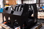
The large bead of an LFAM system dictates the size of features that can be produced. This wall was designed around the width of two full beads of the 3D printing nozzle it was produced with. Source: AES
Large format additive manufacturing (LFAM) is making it easier to produce large-scale tools and end-use products from polymer composite — think layup molds, furniture, full-scale flight simulators and even unpiloted submarine housings.
But even though an LFAM printer is extruding material, much in the same way that a small or medium fused filament fabrication (FFF) printer does, designing parts for this technology is not as simple as scaling up a design that might be successfully printed on a smaller machine. LFAM has its own distinct challenges which must be accounted for not only in slicing and printing, but component design as well.
Additive Engineering Solutions (AES), an Akron-based LFAM power user since 2017, has learned quite a bit about how to design successful prints for its Cincinnati Inc. BAAM machines and, more recently, a robot-based platform from CEAD.
Additive Manufacturing Media Editor-in-Chief Peter Zelinski (center) recently returned to AES to report on the lessons the company is learning about the differences between gantry and robot-based LFAM.
In this piece featured in our sister publication CompositesWorld, AES coowner Austin Schmidt provides practical tips for designing LFAM parts, given these unique process considerations:
- Much larger beads in relation to the part. The typical bead for LFAM is “approximately 1,500 times the cross-sectional area of a traditional [FFF] bead,” Schmidt says, and larger in relation to the part it is building. Bead size and geometry therefore have a more significant impact on the size of features that can be achieved; the width of a thin wall, for example, should be designed to be divisible by the width of the intended print bead.
- Difficulty of dealing with supports. Unlike desktop FFF, where support structures can be easily removed by hand or washed away in the case of dissolvable support materials, LFAM parts are too large to readily postprocess in this fashion. Therefore, designers should lean toward self-supporting structures, and, when incorporating overhangs, keep in mind the part’s changing center of gravity during printing, which can cause tipping.
- Thermal management. The sheer scale of LFAM makes it more difficult to identify and maintain the “Goldilocks” effect where new material is being deposited onto a previous layer that is the correct “recoat temperature” to encourage proper layer bonding.
Related Content
-
Video: Reinforcing (and Joining) Parts After 3D Printing
Reinforce 3D has developed a method that can be applied to strengthen 3D printed parts by feeding continuous fiber and resin through them. The technique also enables joining parts of various materials and manufacturing methods.
-
Eaton Developing Carbon-Reinforced PEKK to Replace Aluminum in Aircraft Air Ducts
3D printable material will meet ESD, flammability and other requirements to allow for flexible manufacturing of ducts, without tooling needed today.
-
Louisville Slugger Uses Formlabs Technology to Accelerate Innovation
Louisville Slugger relies on Formlabs’ Form 3 stereolithography 3D printer to create both prototypes and manufacturing aids for designs of the composite and aluminum bats swung by youth and collegiate players.


.jpg;width=70;height=70;mode=crop)


