Support Structures Hold Down Productivity, Says Velo3D
A build example involving an aircraft bracket illustrates the production rate increase resulting from more parts per build plus the elimination of support removal. A new system for quality monitoring aids production as well.
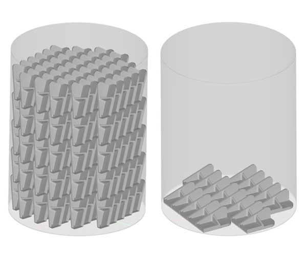
With support structures, 18 parts fit on the build plate area. Without supports, 220 parts float free within the build volume. On the free-floating parts, note the parts' orientation: Starting each part on one point (in this case, a corner) is important for Velo3D's process. Read more in the article below. Image courtesy of Velo3D.
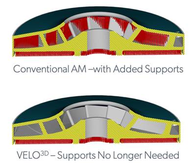
Support structures in additive manufacturing (AM) can anchor a metal 3D printed part against warping from thermal-induced stresses. But those same support structures can hold down something else as well: the productivity of 3D printing and the quantity of parts one build can deliver. According to Velo3D, getting away from support structures — a promise of the company’s “SupportFree” system — is an aid to building at production scale using a powder bed fusion process.
SupportFree is Velo3D’s term for various hardware and software capabilities of its metal AM system that together allow for unsupported overhanging features of a part to print effectively despite the lack of support. Process simulation, control over process variables, a non-contact recoater and feature-specific processing all are part of this. One result of getting away from support structures is that existing parts shifting from conventional to additive manufacturing may not need to be redesigned for AM. But another advantage is the way the absence of supports potentially enables 3D printing build quantities to expand to production scale. I discussed this with solutions engineer Will Hasting during a recent visit to the company’s Campbell, California, headquarters.
He uses an aircraft bracket (a real part design currently made additively) to illustrate the difference. On a 315-mm-diameter build plate, 18 brackets could fit within the build area. But eliminating supports makes the unfused powder sufficient on its own to support the parts as they are forming, opening up the entire build volume for printing. Strategic nesting of the bracket in the 400-mm-tall cylindrical volume above the same 315-mm-diameter plate allows a single cycle to instead run 220 parts.
The build with more parts takes much longer to run, but the productivity gain is significant in spite of this, Hasting says. The set of 18 parts prints in 18 hours, while the 220 parts take about 10 days. The result of those figures is a production rate of 90 parts per week with supports (one build per day, five days per week) versus 147 parts per week without — and that difference falls short of the full savings.
“There is also less touch labor per part in the method without supports,” he says, not just because part unloading happens more frequently given the 18-part build, but also because support structure removal adds extra work, often manual. By contrast, with no support structures, unloading finished parts consists of just pulling them free of the powder, as I discovered during my visit. This is me discovering and unloading 3D printed parts:
The Velo3D system does sometimes require extra stock to be added. The reason relates to part orientation without supports. Unlike other powder bed metal additive systems, Velo3D’s requires the part to begin at a single point. Brackets in the build described above are therefore oriented in a sort of pirouette-style where each part seems to be standing on one corner. Extra stock thus might be necessary not for support, but to ensure the form of the part has one and only one start point. On a small turbine blade including a flange, pictured below, extra stock is added to prevent the tip of the flange from the being a second start point for the same part.
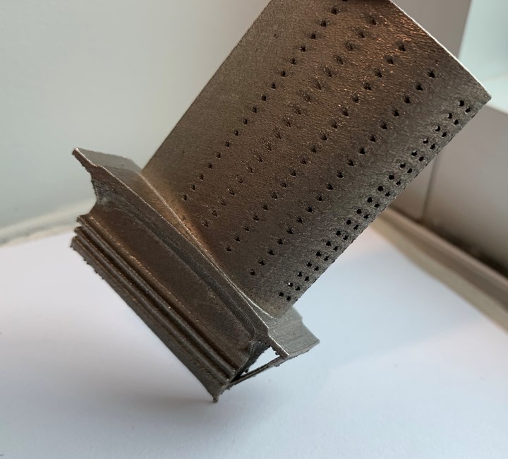
During this part’s build, it is oriented much like this, with a single corner as the start point (the lowest point). The temporary additional stock that is needed can still be seen — it extends from the start point to the tip of the flange. Without this extra stock, the tip of the flange would act as a second start point separate from the ongoing build.
To aid in the application of its platform to repetitive scale production, the company recently introduced its “Assure” system for quality control. One of the challenges of applying AM to production is inspection. Measuring finished parts — the mode of inspection of practically any conventional part-making process — is inadequate to the needs of AM, because postprocess inspection might miss errors internal to the part or errors even more deeply embedded related to inconsistent material formation. Assure therefore inspects the build process to deduce that good parts are being made.
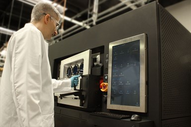
Referring to the Assure system for in-process QA, Will Hasting says, “If the machine is in spec when the build starts and remains in spec through the build, that is the basis for validating quality if a quality part has been produced that way before.” Image courtesy of Velo3D.
Monitoring of in-process variables beyond what is typical of earlier powder bed fusion machines is part of the machine’s system enabling building without support structures. Assure makes use of this same onboard metrology for in-process quality assurance. Parameters tracked include beam stability (a result of cleanliness of the optics), laser alignment, thermal sensor alignment, laser focus and powder bed quality. Explains Hasting, “If the machine is nominally in spec when the build starts and it remains in spec all through the build, then that is the basis for validating part quality if a quality part has been produced that way before.”
One other parameter Assure tracks is one invented by Velo3D, a “defectivity” metric, he says. This is the system’s calculation of the likelihood of defects resulting in porosity within any given region within the part. Velo3D continues to refine the accuracy of this metric through its own testing. Evaluation conducted by Stratasys Direct shows accurate prediction when the metric points to low or high porosity, but further development is required to accurately predict intermediate levels of porosity. If the metric can be further refined into a reliable predictor of hidden defects, then in theory, Hasting says, a user capturing the defectivity data through the course of a build could map this metric in 3D to obtain the virtual equivalent of a CT scan for any part that has just been printed.
Related Content
3D Printed "Evolved Structures" for NASA Exoplanet Balloon Mission: The Cool Parts Show #61
Generative design creates stiff, lightweight brackets for EXCITE mission monitoring planets orbiting other stars. The Cool Parts Show visits Goddard Space Flight Center.
Read More8 Social Media Posts About Additive Manufacturing: AM Radio #34
Cost savings, modifications, large-format AM and more. In this episode of AM Radio, we discuss what people are saying about additive manufacturing on social media.
Read MoreHow AM Enables Cobot Automation for Thyssenkrupp Bilstein (Includes Video)
The shock absorber maker has responded to its staffing shortages through extensive use of collaborative robots. In-house 3D printing makes this possible by providing the related hardware needed to complete the cobot-automated cells.
Read More3D Printed Preforms Improve Strength of Composite Brackets: The Cool Parts Show Bonus
On this episode, we look at a pin bracket for the overhead bin of an airplane made in two composite versions: one with continuous fiber 3D printed reinforcements plus chopped fiber material, and one molded from chopped fiber alone.
Read MoreRead Next
How Machinable Are Support Structures in a Metal 3D-Printed Part?
What happens when you cut away thin-walled supports on your metal 3D-printed part?
Read MoreVideo: Support Structures Are Misnamed! How to Understand Anchors in Additive Manufacturing
Supports or anchors can account for a significant share of both the engineering investment and material use in metal additive manufacturing. Michael Hansen of SLM Solutions discusses the role and importance of support structures.
Read MoreVelo3D: Avoiding Support Structures Means Metal AM Can Be a Solution for Direct Part Replacement
Because of the extent of the redesign they might call for, support structures can be an impediment to AM adoption. Reducing the need for support structures increases the viability of 3D printing for current parts.
Read More

