How Machinable Are Support Structures in a Metal 3D-Printed Part?
What happens when you cut away thin-walled supports on your metal 3D-printed part?
If you have been reading my column, you are aware of the need for and the challenges associated with support structures in additive manufacturing (AM) processes. Support structures are essential for minimizing distortion during the build, but they are difficult to remove because they are made of the same metal as your part.
Despite the need to remove support structures after the build is complete, there are surprisingly few resources published about their machinability. Most studies have focused on the material microstructure and mechanical properties of AM parts instead of determining the best way to machine away support structures encountered in AM.
Many people think that the same strategies used to machine stainless steel, titanium and nickel-based alloys readily translate to structures made with AM, but that may not be the case. Some studies have been conducted of the machinability of solid AM parts made from Ti-6Al-4V and 17-4 stainless steel, but there are subtle differences that are important to keep in mind when dealing with support structures.
If you are being asked to machine support structures, keep in mind that the material you are machining away may not be what you think it is. This depends on how the material was heat-treated (or not), as the AM part may have a different microstructure, and therefore, a different response when it is machined. Furthermore, in most cases, the support structures are not fully dense, meaning they are intentionally porous to save build time and material usage. Finally, the support structures themselves can trap loose powder depending on the geometry that is used.
All of this adds up to a lot of uncertainty when machining support structures away from an AM part. To gain some insight into this, I worked with two of my machining colleagues at Penn State, Professor Edward De Meter and Professor Guha Manogharan, and a team of graduate students to conduct experiments to study the machinability of support structures in Inconel 718 support structures.
The results we obtained surprised us, and I wanted to share some of the highlights with you now that our full paper is available in the Journal of Manufacturing Processes.
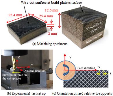
For this study, we designed and fabricated a standard block-type support structure in Inconel 718, varying the height to enable us to study differences in cutting forces and milling behavior. The machining specimens and test setup are shown in Figure 1. The average wall thickness of the supports is 0.11 mm, and the spacing between walls is 0.8 mm—typical dimensions for this type of support-structure geometry.
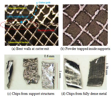
So, what happens when you try and machine away these thin-walled support structures? Well, we found that they do not uproot or cleanly shear when milled, nor do they break away from the base material as they are intended to do. Instead, the supports maintain their structure, and the thin-walls tend to collapse (see Figure 2a).
In the tall supports, trapped powder was revealed inside the support structures as milling depth increased. Despite using high-pressure air to blow out as much of the loose powder as we could before machining, at cutting depths below 2 mm, powder was still trapped inside (see Figure 2b).
As the thin walls are machined, they form localized chips. The chips formed from the support structures were nearly uniform in width (the depth of cut), but their lengths varied based on the position of the tool path relative to the thin-walled region being cut. Examples of chips can be seen in Figure 2c alongside chips from cutting the fully dense material in Figure 2d.
So, supports can be machined, but cutting-force analysis revealed that the specific cutting energy to mill the supports is only 12 percent of what is needed to mill the fully dense material based on swept volume (43 percent difference if material volume is considered). We were surprised that this value was so low, and the machining community will need to reevaluate recommended speeds and feeds for milling different alloys used in support structures.
Do you wonder what happens to the tool itself? Next month, we will take a closer look at the nature of the forces the tool sees and what that does to tool life.
This article originally appeared in Additive Insights, a monthly column in Modern Machine Shop magazine.
Related Content
How to Organize for Additive Production: AM Radio #42
Tim Simpson and Peter Zelinski discuss the next steps for succeeding with AM: After technical and process successes come the cultural, organizational and even costing considerations associated with this mode of manufacturing.
Read MoreUnderstanding PEKK and PEEK for 3D Printing: The Cool Parts Show Bonus
Both materials offer properties desirable for medical implants, among other applications. In this bonus episode, hear more from Oxford Performance Materials and Curiteva about how these companies are applying PEKK and PEEK, respectively.
Read MoreThe AM Ecosystem, User Journeys and More from Formnext Forum Austin: AM Radio #43
Sessions and conversations at the first U.S. Formnext event highlighted the complete additive manufacturing ecosystem, sustainability, the importance of customer education, AM user journeys and much more.
Read MoreAM 101: What Is Binder Jetting? (Includes Video)
Binder jetting requires no support structures, is accurate and repeatable, and is said to eliminate dimensional distortion problems common in some high-heat 3D technologies. Here is a look at how binder jetting works and its benefits for additive manufacturing.
Read MoreRead Next
Alquist 3D Looks Toward a Carbon-Sequestering Future with 3D Printed Infrastructure
The Colorado startup aims to reduce the carbon footprint of new buildings, homes and city infrastructure with robotic 3D printing and a specialized geopolymer material.
Read MorePostprocessing Steps and Costs for Metal 3D Printing
When your metal part is done 3D printing, you just pull it out of the machine and start using it, right? Not exactly.
Read MoreProfilometry-Based Indentation Plastometry (PIP) as an Alternative to Standard Tensile Testing
UK-based Plastometrex offers a benchtop testing device utilizing PIP to quickly and easily analyze the yield strength, tensile strength and uniform elongation of samples and even printed parts. The solution is particularly useful for additive manufacturing.
Read More

