How Additive Manufacturing Is Like (and Different from) CNC Machining
A leading machining business applies the skill of a toolmaker to using additive manufacturing effectively. The manufacturer shares application examples, as well as thoughts on the challenge and promise of this technology.
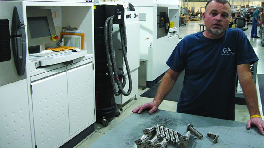
"It’s not plug-and-play,” says Dick Conrow.
Using additive manufacturing to produce precise, functional metal parts is not necessarily easy.
Prospective users could be forgiven for thinking that it is. Terms such as “3D printing” make it sound as though additive technology is as easy to use as a desktop printer—as though the CAD model just needs to be sent to the machine in order for the part to appear.
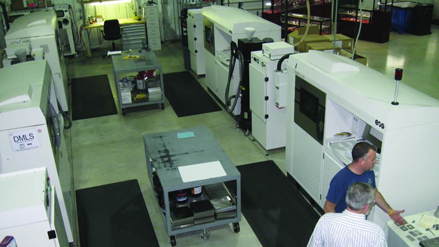
The reality is much different. Just like CNC machining, says Conrow, additive manufacturing is a powerful, sophisticated manufacturing resource that has to be understood on its own terms. His business, C&A Tool of Churubusco, Indiana, has devoted considerable time to developing that understanding. The company bought its first direct metal laser sintering (DMLS) machine five years ago and today uses four of these machines. Part of what C&A has learned is that additive manufacturing, just like the subtractive variety, demands manufacturing expertise.
Common Sense
It is no stretch to say this: C&A Tool is an exemplary CNC machining business. What began in 1969 as “the tool shop on the corner,” in Conrow’s words, has since grown to become a leading source for contract machining of engineered components. Today it employs more than 500 people and occupies facilities totaling more than 700,000 square feet. Swiss-type machining, five-axis machining and precision CNC grinding are a few of the company’s areas of expertise. So are medical machining, aerospace machining, fuel system component production and machining of both tiny parts and massive ones.
Yet despite the company’s continued success in CNC machining, Conrow says embracing additive manufacturing was “common sense.” Part making will move in this direction, he says.
In fact, he’s been watching additive manufacturing for decades. Additive processes in the past could not be trusted to produce airtight critical parts with fine material consistency, he says, but times have changed. The shortcomings that once disqualified additive manufacturing from high-value work have been overcome. Accordingly, he expects additive processes to account for a rapidly growing share of engineered part production going forward. He also expects that C&A Tool will be ready.
Additive Challenges
The shop installed its first DMLS machine in 2008. For more than a year after buying it, the company made practically nothing with it other than test parts. The high-end machine was often used to make trinkets as mundane as bottle openers. This might seem like a tragic underuse of the machine capacity, but in fact the experience was valuable. The knowledge that C&A Tool’s staff developed during this time shapes the way that the company uses its multiple DMLS machines today (all from EOS). At present there are four such machines at C&A, and Conrow is confident that more will come.
What has the shop learned? A great deal. Various factors affect the accuracy and cost of every DMLS build, factors that include:
1. Weight. The part’s weight gradually changes as it’s additively built. How should the part be designed, oriented and supported so it doesn’t distort while growing?
2. Heat. The laser in laser sintering applies localized heat. How can the process account for the effect of this heat so the part doesn’t break tolerance through thermal distortion?
3. Speed. Compared to a CNC machining cycle, an additive build cycle is slow. Can anything be done to moderate this time?
The team at C&A Tool now knows various answers to these and other questions related to additive processing. In fact, the team knows quite a bit more about factors such as these than an article can convey. However, several examples help tell the story. The following part samples illustrate some of the ways C&A is now overcoming the challenges of additive manufacturing and realizing this technology’s promise.
1. Dissimilar Batch
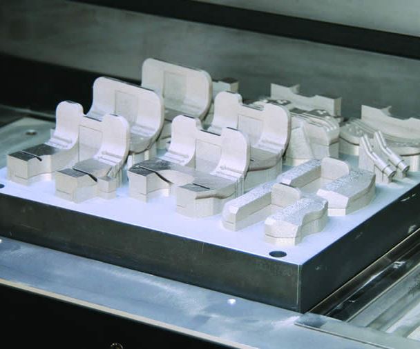
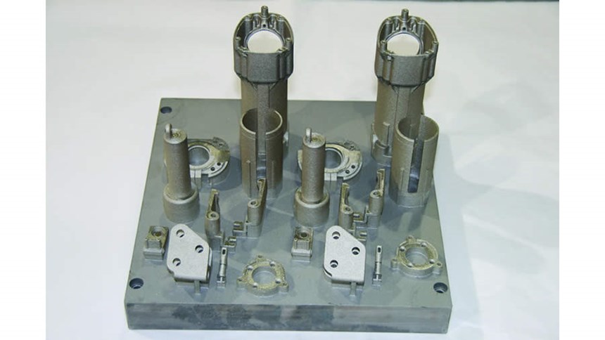
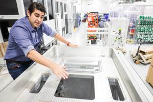
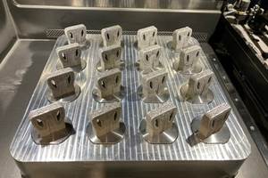
Figure 1, out of the photo set above , illustrates one of the simplest yet most significant process engineering considerations that C&A Tool gives to additive manufacturing. Part of the solution to additive processing’s slow speed is to allow one build cycle to create as many parts as possible, as this photo shows. DMLS creates parts in minute Z-level layers, and the number of these layers affects cycle time. By comparison, increasing the X-Y complexity of each layer has much less effect on cycle time. As a result, nesting more parts onto the build plate provides an effective way to create a time-efficient cycle. For C&A Tool, this even involves combining dissimilar part numbers from unrelated customers so that each customer gets some of the cost benefit.
Conrow likens this strategy to that of an independent truck driver. The trucker wants to pack his trailer with the freight of as many customers as possible before he sets out. The old joke has the trucker saying, “I paid for the whole truck.”
In the same way, Conrow paid for the whole build plate in a DMLS cycle. Space on this plate that isn’t used to grow a part essentially represents capacity going to waste.
Meanwhile, the nesting strategy also addresses one other vexing challenge of additive manufacturing: the difficulty of so-called “rapid prototyping.” DMLS is not always rapid and it is not always cost-effective for making a prototype, but few customers fully appreciate this. Instead, customers frequently come to C&A asking the shop to quickly “print out” a metal part.
Through nesting, C&A can often deliver on this expectation. The quick prototype part that a customer desires can often be slipped into the open space still available on a build that was scheduled to run anyway.
2. Straight Tube
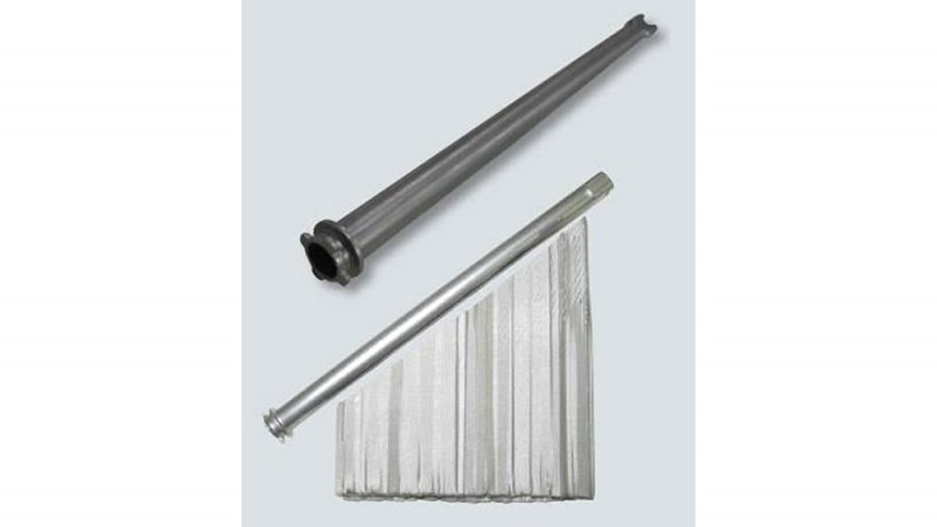
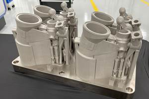
The hollow cylindrical part in Figure 2 is 9.5 inches long and 0.5 inch in diameter, with 0.010-inch wall thickness and an allowable total runout of 0.004 inch. Particularly in light of the integral features at either end of the tube, this part would be challenging to produce through CNC machining. C&A Tool’s staff instead thought about how to produce this part additively, and the nature of their thinking reveals something vital and fundamental about the company’s use of this technology. Namely: Even with DMLS, this is still the tool shop on the corner.
That’s because C&A personnel using additive manufacturing still think like toolmakers—still considering how to achieve and maintain straightness, roundness, location tolerances and so on. It’s just that a process such as DMLS imposes different considerations for how to reach those goals.
Heat is one such consideration. What the outsider often does not appreciate about DMLS is that the design of a precise part such as this long tube might be iterative. That is, after running a trial build to observe how and where the heat of the process distorts the part, the shop might alter the CAD model in slight ways to compensate for that distortion when the final part is built.
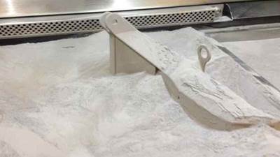
Another consideration is weight. For this tubular component, if the part was oriented on the build plate in the way it would be placed on a table naturally—that is, laying on its side—then the part would sag while being constructed, compromising its roundness. Instead, the way to produce this part accurately was to add risers to the build (seen in the photo) so that the part took its shape at an angle. These risers were thin and easy to remove when the cycle was complete.
Speed was also a consideration for this job, because the customer needed the part quickly. In this case, DMLS was rapid indeed. Knowing how challenging the part would be to make, the customer expected a lead time commensurate with the challenge. The customer was surprised, therefore, after releasing the job on a Thursday, when C&A Tool called back the following Monday to ask where to ship the finished pieces.
3. Medical Device
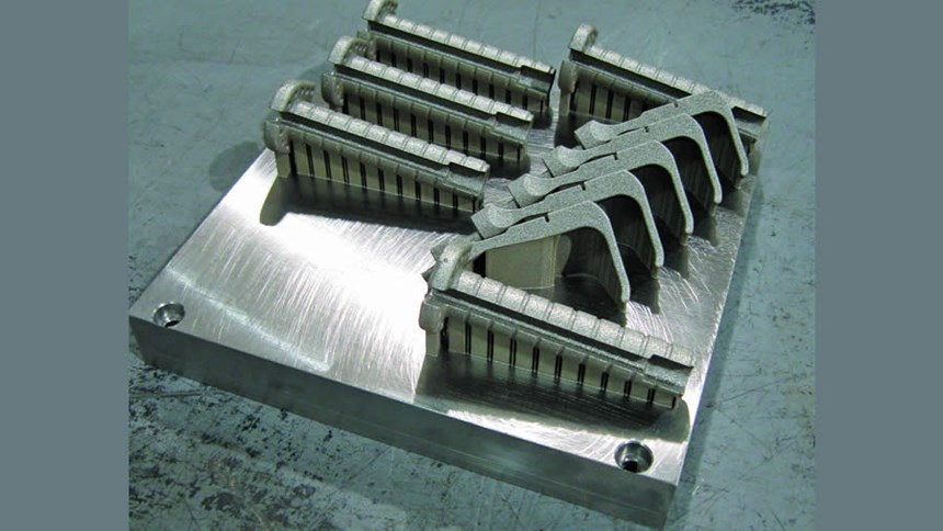
Another key to controlling the duration of an additive manufacturing cycle is to control the height. Again, complexity in X and Y does relatively little to affect cycle time, but increased height in Z directly increases the number of layers the build requires. With the medical implement seen in Figure 3, C&A Tool did not need to divide the implement into the two pieces seen. While division like this is sometimes necessary to get large parts to fit within the machine’s work zone, that was not the case here. Instead, C&A chose to split this part solely as a way to control the cycle time by controlling the height. For precision, the part is built at an angle (like the tubular part in Figure 2), but combining that angle with the full length of this device would have produced a high Z dimension. Instead, the shop kept the profile low by splitting it within the setup shown, which produces five complete tools in each cycle.
Yet even after controlling cycle time this way, the build cycle is still long. Growing the batch of parts seen here took 36 hours. Cycle times like this are typical of DMLS, says C&A’s Tony Stinson, who works with the additive machines. He says this leads to a challenge that users of other manufacturing processes might not regard so seriously: the danger of a power outage.
To produce a seamless build, the additive cycle has to continue uninterrupted, he says. So far, C&A has scrapped few parts because of utility interruption—but it has happened. Stinson says there have been times when he has delayed starting a job until a forecasted thunderstorm has passed beyond the shop’s area. Oddly similar to a farmer, he is prone to checking the weather before proceeding with the work he has planned for the day.
4. Non-Cylindrical Tube
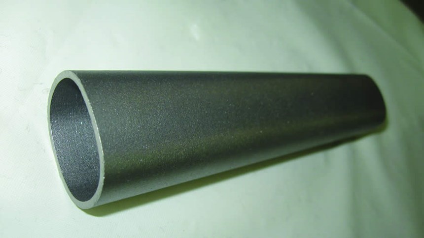
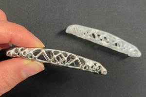
The metal component in Figure 4 with a non-round profile and tapering dimensions was another part that a customer needed quickly. Without additive manufacturing, asks Conrow, how else would this part be made?
In the case of this job, additive manufacturing did not just provide a way to produce the part quickly. It provided the only practical way to make the part at all.
5. Electromechanical Device
The final sample part doesn’t get a photograph, because the job was secret. A customer recently asked C&A Tool to produce nearly all of the components for a proprietary electromechanical device. The order included the housing, gears, connectors, shafts and even nuts and bolts.
All of the components were small enough that C&A was able to nest the complete set of parts onto a single plate for a single DMLS cycle.
The customer representative visited C&A Tool to evaluate the parts produced this way. Seeing the components as formed through DMLS, he picked them up, put them together, combined them with a motor he had brought along and assembled the completed electromechanical device right there on-site. He flipped a switch and the device came to life, functioning as designed.
Conrow considers this to be one of the most eye-opening successes he has seen.
This example continues to affect the way he thinks about additive manufacturing. It affects how far he expects the technology to go. The way to employ additive manufacturing, he says—the way to truly realize its potential—is to see it not as a way to make parts, but as a way to make sets or systems. The components of the electromechanical device, if they had been made some other way, would have needed separate departments within C&A Tool and might even have needed a supply chain. But with additive manufacturing, one machine made everything. No, even better—one cycle made everything.
This suggests the key difference between additive manufacturing and CNC machining, Conrow says. Machining is the way to make one part, such as a gear. Additive manufacturing, he says, is the way to make the entire gear train.
Conrow on Additive Manufacturing
Here are other points about additive manufacturing of metal parts from C&A Tool’s Dick Conrow:
1. Prepare for multiple machines. Given the long cycle times, additive manufacturing machine capacity can easily become a constraint. Even though DMLS activity at C&A Tool is spotty, jobs still have a way of hitting at the same time. Because of this, one DMLS machine was not enough; the shop had to buy more. Fair or not, customers expect “rapid” from additive processes, and Conrow says “rapid” is not consistent with quoting the customer an eight-week wait for open machine time.
2. Lean on machining. Conrow says, “I don’t see how you could succeed at additive manufacturing without CNC machining capability.” An additive-manufactured part in metal usually is not a finished part. Recognizing this, a major OEM in need of additive work recently approached C&A Tool, not because of the shop’s DMLS capability, but because the shop had DMLS supported by machining expertise.
3. Know what to machine. Additive manufacturing can produce a tapped hole, but that doesn’t mean this is the right way to generate that feature. Learning which features to make additively and which to make subtractively allows additive manufacturing to be used that much more efficiently.
4. Learn by failing. One of the most important benefits of C&A Tool’s success over the years is that it has built up some margin to fail. Any shop committed to additive manufacturing should consider how much it can spend on failure and be ready to make that investment. In its first year with DMLS, C&A Tool would often use the model that came with an additive manufacturing RFQ to build that part, even before the shop learned whether it won the bid. The opportunity for practice was valuable, Conrow says, and the failures often taught lessons that were more valuable than winning the job would have been.
Related Content
Seurat: Speed Is How AM Competes Against Machining, Casting, Forging
“We don’t ask for DFAM first,” says CEO. A new Boston-area additive manufacturing factory will deliver high-volume metal part production at unit costs beating conventional processes.
Read MorePossibilities From Electroplating 3D Printed Plastic Parts
Adding layers of nickel or copper to 3D printed polymer can impart desired properties such as electrical conductivity, EMI shielding, abrasion resistance and improved strength — approaching and even exceeding 3D printed metal, according to RePliForm.
Read MoreWhy AM Leads to Internal Production for Collins Aerospace (Includes Video)
A new Charlotte-area center will provide additive manufacturing expertise and production capacity for Collins business units based across the country, allowing the company to guard proprietary design and process details that are often part of AM.
Read MoreDMG MORI: Build Plate “Pucks” Cut Postprocessing Time by 80%
For spinal implants and other small 3D printed parts made through laser powder bed fusion, separate clampable units resting within the build plate provide for easy transfer to a CNC lathe.
Read MoreRead Next
Video: Is Additive Manufacturing a Competitor to CNC Machining?
Not at all, says Renishaw’s Robert Chiari. The manufacturing methods complement one another, which is why many machining facilities are looking to AM.
Read MoreAdditive Manufacturing’s Opportunity in One Word
I want to say just one word to you: brackets.
Read MorePostprocessing Steps and Costs for Metal 3D Printing
When your metal part is done 3D printing, you just pull it out of the machine and start using it, right? Not exactly.
Read More

