Forget What You Know
In small ways and in very big ways, additive manufacturing changes basic assumptions about the design of manufactured parts. Oak Ridge National Laboratory is discovering what the new assumptions should be.
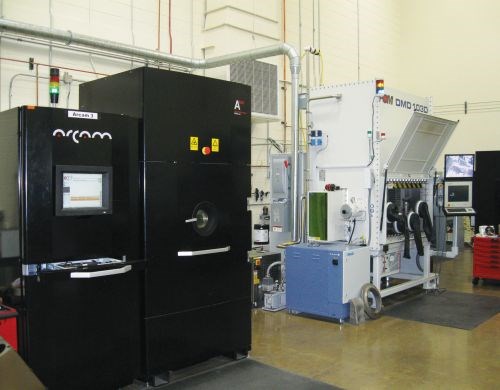
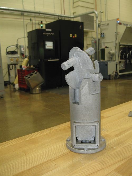
One of the most important sites in the United States for advancing industry’s understanding of additive manufacturing belongs to an institution once associated with the atomic bomb. In Oak Ridge, Tennessee, the Manufacturing Demonstration Facility (MDF)—part of Oak Ridge National Laboratory (ORNL)—is using resources as sophisticated as a $1.4 billion neutron source to examine the material structure of parts produced through direct metal laser sintering, or through electron beam melting performed on the facility’s own Arcam machines.
The resources, technology and scientists in the MDF are all available to help American companies address their manufacturing challenges. Indeed, this is the very mission and purpose of the facility. It was established by the Department of Energy’s Advanced Manufacturing Office in the hope of providing industry with affordable and convenient access to advanced equipment, capacity and expertise. While some of the research done here is initiated by the Department of Defense for the benefit of DoD suppliers, other research is initiated by individual businesses, which enter into cost-sharing research partnerships that tap into the funding the MDF has been granted to assist U.S. manufacturing. The aim of this facility is to provide a conduit so that the technological resources of ORNL—resources bought by U.S. taxpayers—can be applied toward giving U.S. manufacturers a competitive edge.
Additive manufacturing is one of the key research areas here. (Carbon fiber technology is another.) Within the MDF shop, additive manufacturing machines that build in metal and plastic are studied using thermal imaging to chart the processes’ capabilities and performance. One of the goals of the imaging is the development of in-situ process controls. Meanwhile, using ORNL resources located outside this shop, parts produced additively are examined with tools as advanced as neutron tomography to understand their residual stresses. All of this work is directed at improving the effectiveness of additive manufacturing, and ultimately at realizing processes that are controlled and predictable enough for mature, ongoing production of a broad range of critical parts.
Along the way, the researchers involved with this work are expanding their understanding of how to apply additive manufacturing, and growing in their appreciation for what this technology will make possible.
One of those researchers is Ryan Dehoff, Ph.D, who focuses on additive manufacturing of metal components. He says the biggest obstacle to realizing the full value of additive manufacturing might prove to be our established expectations, large and small, about the ways that a manufactured part ought to be designed. Accomplished manufacturing professionals harbor many unseen assumptions about manufacturability that additive manufacturing renders invalid. Are you ready for fluid shapes instead of blockish ones? Are you ready for part geometry itself to slip out of the control of the designers?
In some ways, he says, engineering students are better equipped to apply additive manufacturing than their mentors. The students have not yet been trained in what sorts of shapes they are not supposed to be able to produce.
Therefore, when it comes to additive manufacturing, Dehoff’s message to established manufacturing professionals is essentially this: Forget what you know.
Or more precisely, recognize your assumptions and be prepared to question them.
Additive manufacturing is not a replacement for any existing manufacturing method, he says. Instead, it is a design enabler that will allow engineers to solve problems by “growing” or “printing” components that would have been all but impossible to produce before. However, between today’s engineers and the use of that enabler lies the need for a significant change in mindset. There are various aspects of this change—again, some small and some large. According to Dehoff, here are just a few of the areas in which our conventional expectations about part design will need to give way:
1. Right is Wrong
Take a quick glance at all of the objects around you, and typically you can tell which ones are man-made because of the presence of one feature in particular: right angles. The right angle is commonplace, and it is characteristic of manufactured things. The reason for this is basic. The foundation of most manufacturing is the machine tool, and the easiest form for a machine tool to generate is a right angle. In addition, a right angle is among the easier forms to define on paper for measurement later. For these reasons, an engineer evaluating the manufacturability of a component design will almost invariably, without even realizing it, look for difficulty wherever the design departs from right angles. Departing from straight lines altogether into complex curves makes the design even more suspect.
But this filter is about to become less useful. Additive manufacturing produces organic or complex forms as easily as cubic ones. If anything, the process produces organic shapes even more easily than cubic ones. In recognizing this, we begin to see just how many of the right angles in the world around us are unnecessary. We have many of the square corners we do simply because this is the most natural feature to machine. When manufacturing is based on an additive process, many of those right angles should be abandoned.
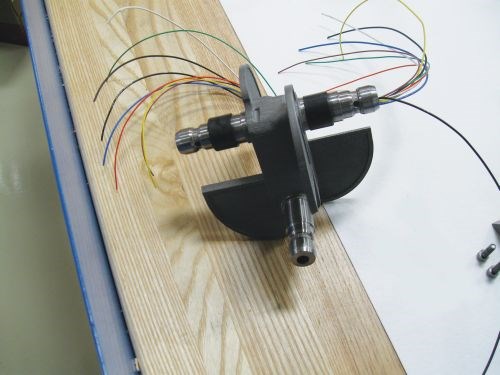
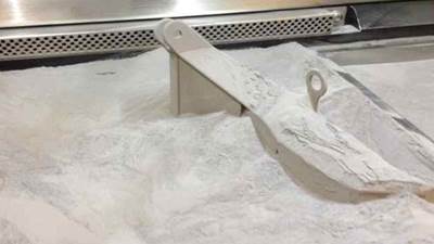
For the MDF team, a robotic hand designed to simulate a human hand served to emphasize this point. The hand was created on one of the facility’s Arcam machines, which employs an additive process in which an electron beam moves through a bed of powder to create each layer of the part. The powder that is not melted by the beam in this process remains in place to support the part as it grows. This support system is elegant, because it conforms to the part and minimizes residual stress, but it also leaves powder packed all through the internal features when the part is finished. Without thinking about their choice, the robotic hand’s engineers had arranged the hand’s internal passages for cabling into a tidy and visually pleasing pattern of straight channels that met at right angles. Getting the powder out of the resulting internal corners proved to be impossible. This problem was solved in the next iteration, when the part was refashioned to give each of the internal channels a gently curving course like a river, removing the unnecessary angles from the design.
2. Anything but Round
Another basic assumption of manufacturability is that we expect holes to be round. This expectation is also natural, because drilling and boring produce circular holes. In additive manufacturing, however, a circular cross-section can be a particularly challenging hole shape.
Here’s why: In an additive process, any feature potentially has to remain stable even while it is incomplete, because features are built up through gradual layering. For a circular hole, this is problematic if the part orientation means the hole has to be grown as it lays horizontally. Maintaining the circularity as the incomplete hole grows is likely to require extra support to be engineered into the design—a wasteful step if that circularity is not actually needed for the hole’s function. Where the hole’s purpose does not depend on the cross section, a diamond-shaped or triangular hole would likely be the more stable choice. Therefore, it is important to ask: Just what is the hole’s purpose?
Indeed, what is the purpose of any feature? Dehoff says this point about hole roundness relates to a larger issue in additive manufacturing: the importance of being aware of design intent. Designers and manufacturers have to be in close communication, he says. Hole circularity is just one example of a detail unthinkingly applied that could result in unnecessary cost.
Of course, communication is needed in CNC machining as well, but the communication here tends not to require the same effort. In machining, any unmachinable feature will become apparent and will lead to a conversation automatically. But in additive manufacturing, there are hardly any “ungrowable” features. Nor is there any established language for communicating which design choices are vital and which forms are just casual or accidental choices. Thus, there is nothing to stop the manufacturer from trying to produce the part precisely according to the received design. This can be excessively expensive.
In one project that ORNL took on, engineers debated the best way to additively produce the most challenging feature of the part model—a 0.003-inch-thick fin. The high price ORNL quoted for the part surprised the designer so much that he questioned it, which was fortunate. It turned out that the thin fin was just an STL error. The client did not want it or even know it was there. Once this “feature” was removed, the part could be reoriented in the build chamber for far more efficient production, resulting in the quoted price dropping by a factor of 10.
3. The New Aluminum
When the choice of material does not matter for a part that is to be machined, that choice tends to be aluminum. The metal is easy to machine and cheap. As a result, engineers frequently specify aluminum as their go-to material, believing they are simplifying manufacturing. But in the current state of additive manufacturing process knowledge, this choice is little help.
As strange as it sounds, Dehoff says the go-to metal for many additive manufacturing applications should be titanium 6-4. From a machining perspective, of course, this choice is bizarre. Titanium 6-4 is relatively challenging to machine, not to mention expensive. But that’s machining. The additive manufacturing perspective is different.
Titanium 6-4 is not hard to work with in an additive process largely because so much work has already gone into fine-tuning additive processes for this metal. Within the Arcam electron beam melting process, for example, this material’s behavior is probably the best understood of any alloy. The build parameters in this and other additive manufacturing processes are well known. In aluminum, this is hardly the case—there has been much less additive manufacturing work with this metal.
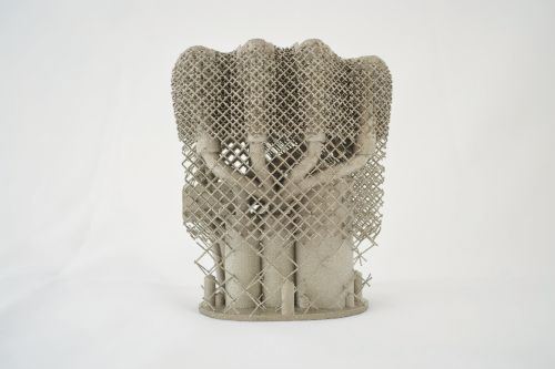
Plus, additive manufacturing actually makes titanium cheap. While the material is still more expensive than aluminum on an equivalent-weight basis, the strength of titanium enables the designer to use far less of the metal to attain the same structural performance. In place of a solid form, for example, a complex mesh structure could be grown within the additive machine so that the part uses only the amount of metal necessary to safely support its intended load. This freedom not only minimizes the weight of the titanium part, but also controls cost to the point of making the titanium component competitive. And in cases where the strength of titanium allows one additively produced titanium part to replace what used to be a complex assembly of multiple aluminum parts, that substitution can deliver significant cost reduction.
4. Function Instead of Form
Of all of the design engineering departures required to realize the potential of additive manufacturing, Dehoff says one final point is the most radical: Engineers should not directly create the designs. Engineers should define needs and constraints instead.
To understand, consider the previously cited idea of using a mesh structure to carry the part’s intended load. Additive manufacturing makes such a structure easy to achieve. That structure could minimize both material cost and part weight compared to making the part solid. However, how would the designer ever create the mesh that precisely realizes this promise? That is, what is the optimal mesh form providing the best achievable performance-to-material-volume ratio? That the engineer could know this is inconceivable, particularly if the load is applied to an organic form at a variety of angles. And it is just as inconceivable that the engineer could create the design directly. Would he manually model each individual strand of the mesh in CAD?
We have never before faced a difficulty like this in manufacturing engineering, because we have never before had the freedom to realize such sophisticated geometric solutions. Previously, component parts have been solid and therefore relatively simple, so we have been able to use relatively simple and direct methods to model them.
In the future, says Dehoff, design engineers will model performance objectives instead of the actual manufactured forms. Rather than directly constructing the model in CAD, the engineer will define load requirements and other performance factors in detail, and also define design objectives related to weight, cost and build time. From this boundary information, software will calculate and generate the ideal part geometry model—the form that will ultimately be grown through 3D printing.
Software is available that works on something like this principle today. Design engineering tools using this approach will need to be in much more widespread use, Dehoff says. Computing power will be a factor, because large parts with complex performance requirements will pose extreme computational demands. In short, the real challenge of additive manufacturing comes from the fact that, with its arrival, manufacturing technology has now outraced the tools and even the knowledge that design engineers have available. We can now produce what we are not yet ready to conceive. The manufacturing technology is that far ahead. For the use of additive manufacturing to expand, our thinking about design engineering just needs to catch up.
Related Content
Seurat: Speed Is How AM Competes Against Machining, Casting, Forging
“We don’t ask for DFAM first,” says CEO. A new Boston-area additive manufacturing factory will deliver high-volume metal part production at unit costs beating conventional processes.
Read MoreAirless Basketball Shows Promise of 3D Printed Lattices: The Cool Parts Show Bonus
Successfully matching the performance of a standard basketball demonstrates the control possible over the mechanical properties of digital materials.
Read More3D Printed Lattice for Mars Sample Return Crash Landing: The Cool Parts Show Bonus
NASA Jet Propulsion Laboratory employs laser powder bed fusion additive manufacturing plus chemical etching to create strong, lightweight lattice structures optimized to protect rock samples from Mars during their violent arrival on earth.
Read MoreFlexible Bellows Made Through Metal 3D Printing: The Cool Parts Show #64
Can laser powder bed fusion create metal parts with controlled flexibility? We explore an example in this episode of The Cool Parts Show.
Read MoreRead Next
Postprocessing Steps and Costs for Metal 3D Printing
When your metal part is done 3D printing, you just pull it out of the machine and start using it, right? Not exactly.
Read MoreAlquist 3D Looks Toward a Carbon-Sequestering Future with 3D Printed Infrastructure
The Colorado startup aims to reduce the carbon footprint of new buildings, homes and city infrastructure with robotic 3D printing and a specialized geopolymer material.
Read More3D Printed Polymer EOAT Increases Safety of Cobots
Contract manufacturer Anubis 3D applies polymer 3D printing processes to manufacture cobot tooling that is lightweight, smooth and safer for human interaction.
Read More

