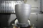
On the first episode of our video series “AM: Why the Failure?” to deal with directed energy deposition (DED), Penn State professor of additive manufacturing Tim Simpson and I discuss a component intended to be a nozzle that developed a crown-like form during 3D printing.
The part accidentally came to resemble a chess piece. What was the cause of this error?
Guesses in social media focused on software or programmed motion paths, but the true cause was thermodynamics. Heat was not able to escape the part fast enough.

The melt pool therefore grew too large at the six different start points around the part’s various circular layers, producing six different high points. Tim discusses some of the remedies for this problem. | This episode of AM: Why the Failure? brought to you by Verisurf
Related resources:
Transcript
Peter Zelinski
Why the failure is sponsored by Verisurf inspection and measurement software. Stick around after the episode to learn more.
Peter Zelinski
Welcome to Why The Failure? This is our video series about additive manufacturing builds gone wrong. My name is Peter Zelinski. My expert co host is Penn State professor of additive manufacturing Tim Simpson. Tim, thanks for joining me again.
Tim Simpson
Hey, great to be here, Pete. Thank you.
Peter Zelinski
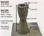
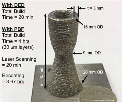
Alright, so this is our third episode in the series, but this is going to be our first episode where we talk about directed energy deposition. In the previous two episodes, we looked at laser powder bed fusion, go check those out. Directed energy deposition, it's not just the laser moving to 3D print a metal part, but it is a process instead using blown powder or fed wire stock material. And the entire workpiece the entire part might move underneath that nozzle or the entire nozzle might move in order to build the part. And we're going to look at a failed build for this part. But first, this is the part as it should be. Tim, What is this thing?
Tim Simpson
Yeah, it's a little sort of a notional rocket nozzle, sort of design that we print as part of our industry practicum that we hold at Penn State. So as industry training, comes in there we lecture and talk about how directed energy deposition works, and particularly laser powder feed, and then we go and we can build that very quickly in the afternoon session. So it's a great demo part that we've been using and building for several years now in CIMP-3D.
Peter Zelinski
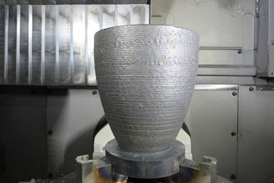
Now here is the failed build, and in a lot of ways, this is geometrically more interesting than the build that was intended. This regular kind of crown feature here, it makes it look a little bit like a chess piece, not a nozzle. Tim, that feature is not supposed to be there. Is it?
Tim Simpson
Correct. Yeah, I thought it was kind of funny you thought the chess piece was what we were trying to build. But no, it's supposed to be nice and flat and level on the top there. So by the time this was done, it came out looking very different from the the program that we fed to the the DED system to print it.
Peter Zelinski
Alright, so this is an error. How did this crown form get there? Let's go to social media now. And the way we do this, if you haven't seen this series before, we use the hashtag #AMWTF in LinkedIn. We debut our fails there, and we let experts observers in the social media community make guesses about what went wrong here. And this time, Tim, a familiar culprit got the blame.
Tim Simpson
Absolutely, love seeing "Hey STL," it was a file conversion as we exported and tessellated our CAD file into STL to then slice and build prep. I don't know, this is becoming a regular habit throwing STL under the bus here, but not the culprit in this case.
Peter Zelinski
There were responses that spoke to software or toolpath challenges that did kind of come closer, because they're more related to DED. Can you can you talk about that?
Tim Simpson
Yeah, I think several of the guesses there sort of started to hone in on that. And I think that's one of the big differences or sort of new potential sources for failure with DED. So even though you're using laser, and even though you're using powder, sort of the way it's interacting, and the motion that's going on the tool pathing, etc, the mechanics, the physics, the heat transfer, end up being a bit more complex in DED sort of processes. And so you look at, you know, a couple of guesses, Taras Kosteniuk from InssTek, talking about looking at the border there, perhaps something with the inert gas that caused some disruptions or disturbances, maybe even actually an error in the CAM software itself, that does the slicing and toolpath. Maybe it didn't interpolate the circle correctly as an example. But if you look at, for instance, the other builds there, the other circles, you know right away that it wasn't... It knows how to interpret a circle, that wasn't the issue. The other one, of course, Jacob Steinberg, there at Raytheon was familiar with some of the systems we have at CIMP-3D at Penn State. We actually have a 5-axis DMG MORI hybrid system that does both add and subtract together, and maybe thought as part of the feeds and speeds, again a toolpath issue there, that some additional programming work might be needed and or breakdown in some aspect there. But this was actually not made on that system. This was made on an Optomec Lens system that we've had in the in the lab for well over a decade now.
Peter Zelinski
So let's get at what really happened. Matthew Duffy of Action Mold & Machining made a return appearance and his response caught both our attention, because he was really on the right track. Can you can you share his response?
Tim Simpson
Absolutely. I think you captured it really well in the picture there, the nice close close up, that Matthew noted as well is this is a progressive, sort of build up. And if you look sort of side by side, you can see on the failed one, that sort of waviness, that ends up looking like the, you know, the parapets on a castle on your rook piece actually start building right about that neck, that narrowing area. And as it goes up, it gets progressively worse and worse, until eventually that top layer there that is created. And so the error there coming back to perhaps an inconsistent feed rate, the deposition head movement that is getting progressively worse over time.
Peter Zelinski
Alright, so in the social media conversation, is there a response that came really close?
Tim Simpson
Yeah, I think Daniel Driscoll's response there was probably the closest. You know he also noticed sort of the runaway error of building up progressively one layer to another and attributed it to, you know, powder capture efficiency. And I think that's really what happens, or one of the things that you can run into with DED that you don't with powder bed fusion. As you are building up layers there, right, the heating, the toolpath, the melt pool size, all of that changes at each layer there, depending on the thickness, the geometry, and those sort of aspects, which then influences how much powder that you're blowing in is captured in that melt pool. And as in this case, as it's going around and around, if that melt pool varies, then the amount of powder capture varies, that then leads to some differences and inconsistencies. And so it's not like a powder bed system, because you're not recoding and spreading a single even layer, you're just depositing that. And so as you go along, you can start to get uneven layers that are not going to cause a collision, that will just continue to build up and get worse and worse and worse with a DED process.
Peter Zelinski
Okay, so this is a heat transfer issue, not getting enough heat out of the part results in varying melt pool size. And this, the crowning is an accidental result of the fact that there are six different stop restart points at different layers. As we progressively build this part. There's another difference between the correct part and the error part that I want to point out because since this is a heat transfer issue, these build plates are different thicknesses, the base plates, is that significant here? Was the base plate and heatsink?
Tim Simpson
Actually, yes, in DED the substrate, as we call it, on which you're building is sort of a small build plate. And in some cases, that actually might be part of the part. In this case, we're building the nozzle on the top of that. And as you can see, we had some slightly thinner substrate material that we use for that particular build, and that helps to conduct heat away from the part as it is being built up there. The other challenge or thing that you will note is the amount of heat and the rate at which you can heat conduct heat away is different because of that build plate. And you also look at where it is that the differences start to occur, right? It's the necking section there. So the amount of heat that you're putting in, in a small cross section versus that, means there's less dwell time between this layer and the next, and so you're adding more and more heat much more quickly as you start to neck down. And so you get this compounding effect that leads to the differences in powder capture rate, which then leads to the differences in layer height.
Peter Zelinski
In DED, what you're saying is that the geometry of the part influences the heat transfer that in turn influences how that part itself comes out. I think that's significant because you shared one more component that we can talk about and it's really simple. It's this right angle form but it's a thin wall meeting a thicker wall, and that geometry difference in itself influenced this build. Can you talk about that?
Tim Simpson
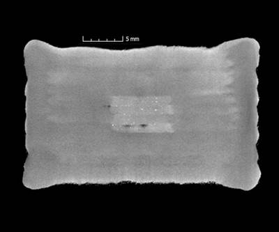
So absolutely, that's a little test coupon that some of the staff in our Applied Research Lab have printed, to start looking at some of the feedback control that's needed to mitigate these changes. So just in that simple one, if you are not changing power and speed, as you go from a thin to a thick wall, the heat conduction, the heat transfer is going to be different, right? You've got more mass in a thicker wall than a thin wall. So if you're not adjusting your energy input, you know, again, laser power and speed, then that difference in heat transfer is going to lead to different efficiencies and powder capture, which lead to differences which manifest in terms of different build heights. So a thinner wall is going to conduct it out, it's going to spread more versus a thicker wall, you don't get as quick a spread of the heat and tends to build up a little bit higher as you go if you are not changing or adapting your toolpath, essentially, your deposition path feeds and speeds in this case.
Peter Zelinski
So what you're saying is the geometry of the part itself affects heat transfer in a way that influences the success of building that very part. So on a component like this nozzle, how do you account for that?
Tim Simpson
Yeah, great observation, Pete. And I think and typically what you would do, just like in laser powder bed fusion, you don't always start and stop at the same point. And so within this case, you can actually see we start and stop at each layer, we sort of increment over and start and go, increment over start and go. And guess how many times we do that, right? It's the same as the number of nozzles there are. And so if you start at different positions and go around in this case, because that heat transfer varies, you're going to start getting slightly higher peaks earlier, when it's not as hot versus later, if you can't get all that heat out quick enough, the end result is the layer height is higher, versus what you had planned. And it's going to progressively get worse and worse as you increment around and do multiple starting points for each different layer.
Peter Zelinski
You saw that, you got this error, then what change did you make that that gave you successful nozzles from that point forward.
Tim Simpson
So to mitigate this going forward, we made sure to have a thicker build plate to again help conduct heat away, we can also raise the temperature a little bit with inside the chamber there, you can change the dwell time, essentially start and stop time between layers to allow a heat to conduct away or to cool down a little bit. And so you start managing the thermals in the process, just like you manage the powder feed and the geometry there. And of course, that's where a lot of research now is in these sort of closed loop systems. Let's sense the temperature, let's sense the height, let's sense the powder flow rate to then make sure that we're building the right part over and over and over again, each layer.
Peter Zelinski
Alright, so a geometry error that was no fault of the geometry modeling or the software, but instead an issue of managing the thermals, just as you said. Why don't you tee up our next episode? What is the failure we're going to see next?
Tim Simpson
Great, yeah, no, we're gonna go back to laser powder bed fusion next episode there and actually take a look at how, as you try and mitigate one failure, you might some new possible failure mechanisms there. So a series of successive build failures, where we tried to change a little geometry, change some process parameters, and just unearth some different opportunities for failure that, unfortunately becam quite painful but a good learning opportunity.
Peter Zelinski
All right, stay tuned for that successive, cascading, dig a hole of successive build failure. That's what we're going to talk about in the next episode. Follow the #AMWTF hashtag in LinkedIn. We are going to debut the failure there first, let you guess. We hope to hear from you. Maybe your answer appears on the next episode. Thanks for watching.
Peter Zelinski
Thank you to our sponsor, Verisurf, a measurement solutions company. Use Verisurf software as a common measurement platform across the enterprise for analysis of parts made through additive manufacturing and other operations. capabilities include quality and inspection reporting, advanced surface analysis and reverse engineering. Built on powerful CAD CAM, Verisurf employs digital model based definition, open standards, universal compatibility with CMMs and comparison of measurement data to nominal 3D CAD or STL files. Regardless of operation, 3D printing, machining, casting or molding, Verisurf supports the process by verifying the part. Maintain the digital thread through design, engineering, manufacturing and part validation. Learn more Verisurf.com
Related Content
Baker Hughes Successfully Implements Oqton Manufacturing OS System to Optimize Additive-Driven Manufacturing Workflow
3D Systems say this successful implementation demonstrates its Oqton Manufacturing OS’ ability to accelerate the design and production of additively manufactured parts across the entire manufacturing workflow to increase efficiency and facilitate regulatory compliance.
Read MoreConocoPhillips Sees Oil and Gas Supply Chain Opportunity With Additive Manufacturing
Production of parts when needed and where needed can respond to the oil and gas sector’s multibillion-dollar challenge of holding parts in inventory. The supply chain benefit will justify additive even before the design freedoms are explored.
Read More3D Printed Seal for Geothermal Power: The Cool Parts Show #73
Plugging a hole is a complex challenge when it’s a well for geothermal power. Additive manufacturing produces a shape-changing stainless steel seal for high-temperature applications deep underground.
Read MoreVideo: 5" Diameter Navy Artillery Rounds Made Through Robot Directed Energy Deposition (DED) Instead of Forging
Big Metal Additive conceives additive manufacturing production factory making hundreds of Navy projectile housings per day.
Read MoreRead Next
Three Cool Uses for Directed Energy Deposition
Most machining professionals don’t like to admit that they ever make mistakes, but every now and then wouldn’t it be nice to have an “eraser” to go back and repair a gouge or fix a nicked edge? Or maybe you took off a bit too much material on that last machining pass and you’d like to add it back? Well, directed energy deposition (DED) enables you to do that and more.
Read MoreWhat Is Directed Energy Deposition?
Analyzing directed energy deposition and powder-bed fusion provides a thorough understanding of the extra machining necessary for a “near-net shape” versus a “net shape” manufacturing process.
Read MoreVideo: Programming for Additive Turning of Cylindrical Parts
Directed energy deposition while the part is spinning enables a means of 3D printing axially symmetric parts. The operation is like CNC turning with material added instead of machined. Open Mind discusses programming the machine paths for this type of build.
Read More

