Can My Machine Tool Access My Support Structures?
Analyzing the machinability of support structures opens a new way of thinking about optimal build orientation.
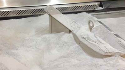
Support structures are a pain for metal parts additively manufactured with laser powder-bed fusion. As much as you would like to redesign or orient your part in a way that avoids needing support structures altogether, invariably, you are going to have deal with them at some point. Wouldn’t it be nice to know how easy they are to access for machining and finishing operations? It would also be nice to know if your available machine tools are not going to be able to access them through that intricate geometry that you are additively manufacturing.
Luckily, I had the good fortune of reconnecting with Dr. Matthew Frank, a Penn State alumni who is now an associate professor at Iowa State University. Dr. Frank’s graduate work focused on using CNC machining for rapid prototyping, specifically, automating subtractive manufacturing processes to compete directly with additive manufacturing. You can find several of his papers online (for example, “Rapid Planning for CNC Machining” and “Subtractive Rapid Prototyping”), but that is not what I want to share this month. It is how he and Dr. Niechen Chen, his former Ph.D. student who is now an assistant professor at Northern Illinois University, adapted those algorithms to analyze the machinability of support structures for AM parts. As you might guess, this opens a whole new way of thinking about optimal build orientation.
Finding the best build orientation for an additively manufactured metal part requires resolving the tradeoffs between build time, support structures, thermal distortion and many other competing objectives. Minimizing build time requires minimizing build height, but this will often lead to excessive overhangs and extensive support structures. Minimizing support structures is certainly desirable, but without sufficient supports, the part may warp as it is built, which can lead to a build failure. Finally, minimizing thermal distortion requires extensive computational analysis to find the best build orientation, and many times extensive support structures are required to reduce distortion.
With Dr. Frank and his research team’s latest work, we can now quickly analyze the accessibility, and hence the machinability, of support structures in all of these possible build orientations and use that information to help decide the best way to orient the part. To accomplish this, Dr. Frank combines ray-tracing algorithms and visibility analysis to determine whether a surface of the part can be accessed by a tool of a given size or shape. His software reads in an STL file and analyzes whether each triangle is visible to the “rays” that are projected and whether they are accessible. The diameter of the ray corresponds to the size of the tool, and the offset of each triangle from the outer boundary correlates to the cutting depth of the tool.
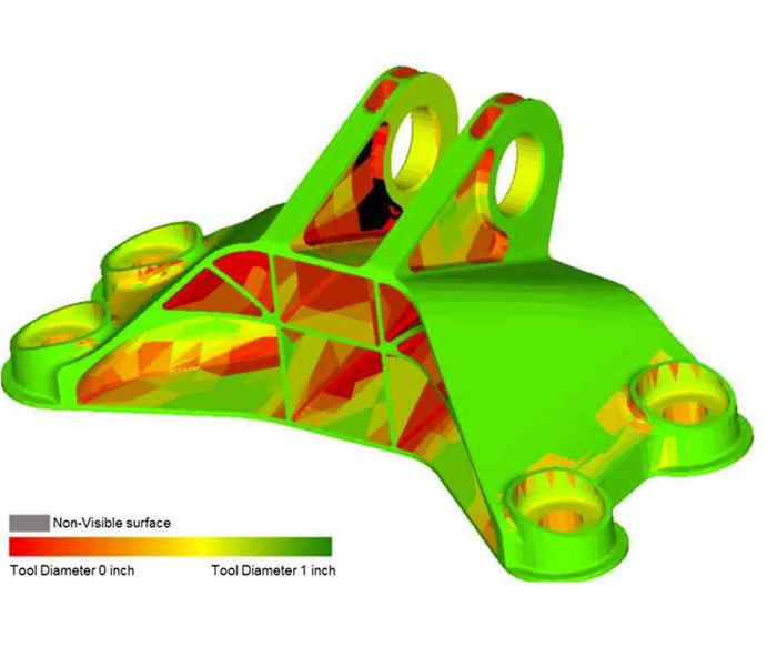
By performing this analysis for a set of cutting tools, you can quickly generate what Dr. Frank calls a tool accessibility map. Figure 1 shows an example for the GE engine bracket that was offered in a design challenge on GrabCAD.com. The color mapping in the figure shows what can be accessed by the available machine tools, with green being easy to access and red requiring smaller tools or limited access. Areas in gray indicate regions that are not visible and, therefore, cannot be accessed by a machine tool.
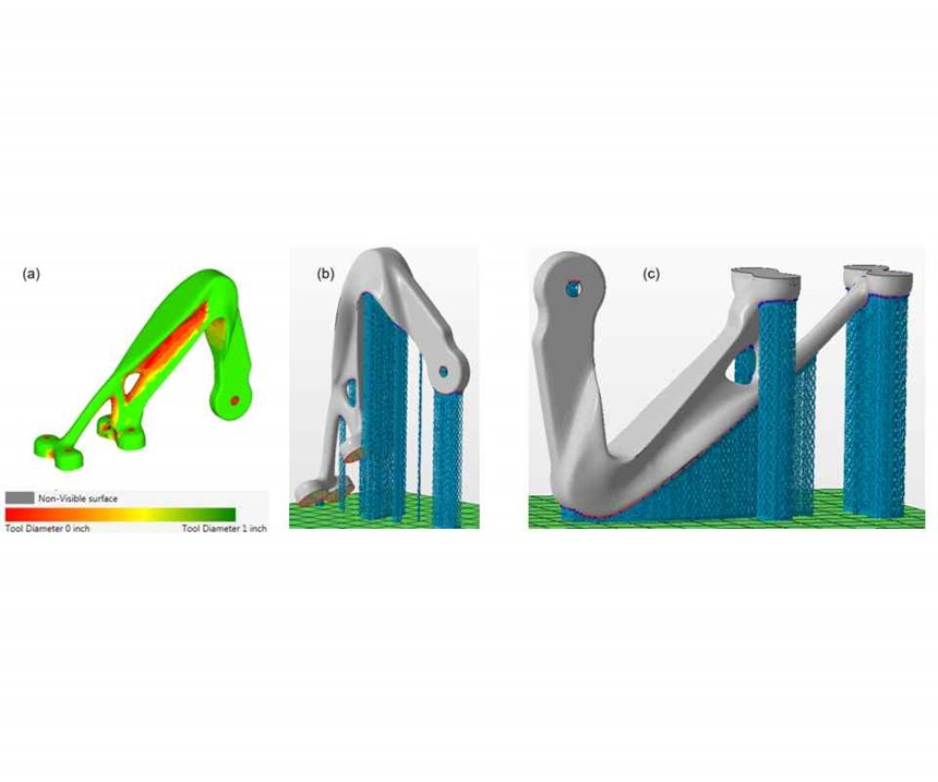
This information is helpful for build-orientation analysis. Figure 2 shows the a design from the Alcoa airplane bearing bracket challenge organized by GrabCAD.com. You can see in the figure how different the recommended build orientations are if you want to minimize thermal distortion or maximize machinability of support structures.
For novice designers and those new to AM, analysis tools like this are important to help identify the impacts of different build orientations. Granted, you may still encounter issues machining the support structures themselves (see my August 2018 column), but at least you will know whether you can access them in your intricate AM geometry.
For more information about this tool accessibility and machinability analysis algorithm, feel free to contact Dr. Matthew Frank directly at mfrank@iastate.edu.
This article originally appeared in Additive Insights, a monthly column in Modern Machine Shop magazine.
Related Content
3MF File Format for Additive Manufacturing: More Than Geometry
The file format offers a less data-intensive way of recording part geometry, as well as details about build preparation, material, process and more.
Read More3D Printing with Plastic Pellets – What You Need to Know
A few 3D printers today are capable of working directly with resin pellets for feedstock. That brings extreme flexibility in material options, but also requires greater knowledge of how to best process any given resin. Here’s how FGF machine maker JuggerBot 3D addresses both the printing technology and the process know-how.
Read MoreImplicit Modeling for Additive Manufacturing
Some software tools now use this modeling strategy as opposed to explicit methods of representing geometry. Here’s how it works, and why it matters for additive manufacturing.
Read MorePostprocessing Steps and Costs for Metal 3D Printing
When your metal part is done 3D printing, you just pull it out of the machine and start using it, right? Not exactly.
Read MoreRead Next
Bike Manufacturer Uses Additive Manufacturing to Create Lighter, More Complex, Customized Parts
Titanium bike frame manufacturer Hanglun Technology mixes precision casting with 3D printing to create bikes that offer increased speed and reduced turbulence during long-distance rides, offering a smoother, faster and more efficient cycling experience.
Read MoreAlquist 3D Looks Toward a Carbon-Sequestering Future with 3D Printed Infrastructure
The Colorado startup aims to reduce the carbon footprint of new buildings, homes and city infrastructure with robotic 3D printing and a specialized geopolymer material.
Read MorePostprocessing Steps and Costs for Metal 3D Printing
When your metal part is done 3D printing, you just pull it out of the machine and start using it, right? Not exactly.
Read More

