3 Design Techniques for High Speed Extrusion 3D Printing
Simple design changes can reduce build time and improve part quality in this production-speed polymer AM process.
Editor’s note: “High Speed Extrusion” (HSE) is Essentium’s rapid deposition process for 3D printing polymer parts at production speeds. It is fused filament fabrication (FFF), but the speed means even the design considerations appropriate to FFF may not be sufficient for this process. Tom Mulholland describes the design considerations for HSE.
While there are many design tips and techniques for additive manufacturing (AM) to be found, such as tips for FFF, selective laser sintering (SLS) and stereolithography (SLA), these design tips are not always applicable to filament printing for High Speed Extrusion, which is a distinct process. Here we look at some design tips that will specifically help design for HSE to achieve faster print times without sacrificing quality or repeatability.
1. Avoid Sharp Corners
Cornering refers to the behavior of the toolhead as it goes around a corner, or changes direction in the XY plane. When it comes to design, the goal is to strategically adjust corners to allow the toolhead to maintain maximum speed.
When designing parts for HSE printing, there is no added time or expense to adding fillets (the rounding of corners). The rule of thumb is to make the fillet radius greater than or equal to 5 millimeters and using high resolution STL files during the design process. This allows the toolhead to move fast while maintaining geometric accuracy.
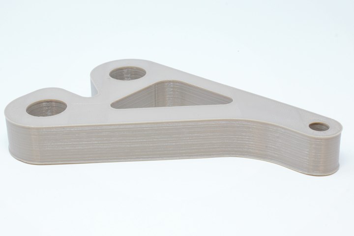
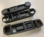
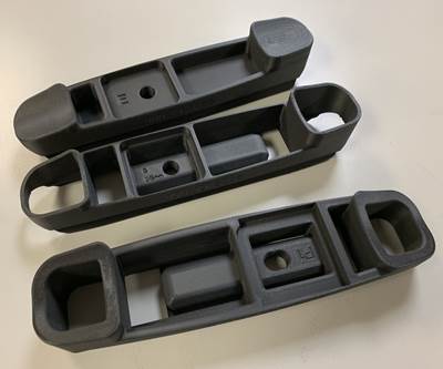
Rounded corners, such as those in this 3D printed bracket made of PEEK, help reduce build time in High Speed Extrusion.
The rationale is that any corners sharper than this require the printer to decelerate and then accelerate again, much like a car slowing down as it negotiates a corner. In a recent case, we saved 15% in print time by adding fillets to a fixture, which previously took 105 minutes to print. That’s impressive for one part, but imagine the time savings for hundreds or thousands of parts using this simple design technique.
By avoiding sharp corners in the part’s design, manufacturers not only reduce print time but also maintain a consistent print speed for the best quality parts.
2. Optimize Travel Movements
Travel movements are transitions between unconnected areas of material deposition. With HSE, travel movements can have a significant impact on print time.
3D printing processes like SLA have travel movements in the Z direction, but in filament printing and HSE, the travel movements are in the XY plane. This means travel movements take place on every layer, so the effect is multiplied by the number of layers in a similar cross-section.
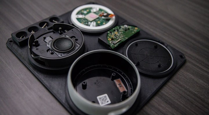
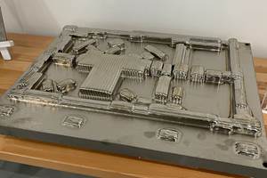
This assembly fixture 3D printed in 5 hours via HSE would have required over 19 hours on a convention FFF printer.
The key to optimizing travel movements is to minimize the number of islands. Connecting otherwise disconnected areas ensures a more consistent extrusion rate, which will improve the quality, enable faster printing, and help avoid defects like stringing and blobbing.
3. Plan Toolpaths for Thin Walls
In planning the toolpath for High Speed Extrusion, engineering designers need to consider the way the printer will lay down the material.
When designing a thin wall, they should think about designing in multiples of the extrusion width, or the nozzle diameter that they’re going to use. For instance, on the Essentium platform, we generally use 0.4-mm nozzles and 0.8-mm nozzles, which means our toolpath width is going to be the same, 0.4 or 0.8 mm.
Avoiding uneven extrusion ensures the best quality and the best strength for part walls. The payback in terms of time savings is also significant — just by switching to wall dimensions in nozzle diameter multiples, we realized a 17% reduction in print speed on a recent chip tray printed through HSE.
Related Content
How Norsk Titanium Is Scaling Up AM Production — and Employment — in New York State
New opportunities for part production via the company’s forging-like additive process are coming from the aerospace industry as well as a different sector, the semiconductor industry.
Read MoreAdditive Manufacturing Is Subtractive, Too: How CNC Machining Integrates With AM (Includes Video)
For Keselowski Advanced Manufacturing, succeeding with laser powder bed fusion as a production process means developing a machine shop that is responsive to, and moves at the pacing of, metal 3D printing.
Read MoreDMG MORI: Build Plate “Pucks” Cut Postprocessing Time by 80%
For spinal implants and other small 3D printed parts made through laser powder bed fusion, separate clampable units resting within the build plate provide for easy transfer to a CNC lathe.
Read MoreHow Machining Makes AM Successful for Innovative 3D Manufacturing
Connections between metal 3D printing and CNC machining serve the Indiana manufacturer in many ways. One connection is customer conversations that resemble a machining job shop. Here is a look at a small company that has advanced quickly to become a thriving additive manufacturing part producer.
Read MoreRead Next
6 Reasons to Use Plastic 3D Printing
Smaller batches and shorter lead times are just two of the benefits of 3D printing parts in plastic. Here are six reasons to choose polymer additive manufacturing (with examples).
Read MoreHow Additive Manufacturing Is Expanding the Possibilities for Plastics
In terms of lead time, part size, quantity and inventory needs, the limitations on plastics are being overcome. We will see plastics doing more — the theme of several recent articles we’ve posted.
Read MoreLinear Motor Platform Delivers Speed, Low Part Cost for Production AM
Essentium’s additive manufacturing machine based on semiconductor manufacturing has as much in common with precision machine tools as with other FFF 3D printers.
Read More
