Topology Optimization Delivers Nonintuitive Design Features for Legacy Part (Includes Video)
Refurbishing a legacy turbine engine for energy efficiency provided the opportunity to demonstrate topology optimization in concert with metal 3D printing. The design for this torque arm comes from computer simulation insight refined with a human touch.
The torque arm on the right side of this bell crank assembly for a turbine engine was redesigned using topology optimization and human insight to deliver a final component that both resembles its predecessor and departs from the historic features of this part. Read on or jump to the video below for the full story. Images: Advatech Pacific
Additive manufacturing (AM) has been touted as a production method for legacy components, or replacements for parts that are no longer in production. Design prints or files are often not available for legacy parts, and in the case of molded or cast components, the necessary tooling likely no longer exists. AM can be used in combination with reverse engineering strategies for such parts, making it possible to reproduce them without the original plans or tooling.
But sometimes a faithful reproduction isn’t the goal. Advatech Pacific, an Arizona-based engineering firm, recently worked on a project to update legacy gas turbine engines to be deployed in new markets. 3D printing was selected to help replace legacy parts for these engines not only because the process could quickly produce the small volumes needed without the use of tooling, but also because AM afforded the opportunity to improve the efficiency of the engines. Combining topology optimization with metal 3D printing enabled Advatech to update many of the engine components with designs that use less material and are lighter than their conventional counterparts.
Topology Optimization for Lightweighting
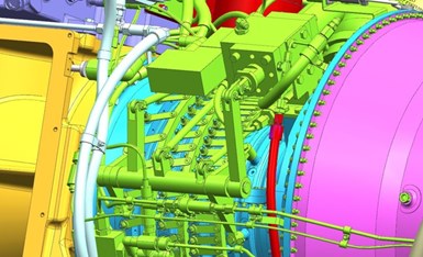
The full bell crank assembly for the turbine engine. The torque arm is visible in green, standing nearly vertically just right of center.
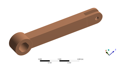
The original torque arm model in ANSYS. Extra material was digitally added before performing the optimization to give the algorithm a larger design space to work in.
To demonstrate the benefits of this two-pronged approach, Advatech Pacific Engineering Manager Matt Humrick selected a simple turbine component: a torque arm that connects the engine’s linear actuator to its bell crank. The original arm is a machined stainless steel component about 7 inches long, with interfaces at either end. The solid piece of metal is subjected to a transverse load in use; it requires strength and stiffness, but in its original design it carried more weight than necessary. To optimize this part and reduce its mass, Humrick used ANSYS, a software package that features simulation tools for analysis, design and manufacturing.
The first step was to build a model of the torque arm in ANSYS within its bell crank assembly, with surface contact specified between each part interface, so that the software would have context for the part in use as well as its rough geometry. Faithfully representing the torque arm itself wasn’t necessary, Humrick says; instead, this first model resembles a slightly larger version of the machined part and serves as a guide for the optimization.
“You want to give the software as much freedom as possible,” Humrick says. “One way you can do that is by giving it a larger material envelope to work with.”
Once the model was complete, Humrick set the optimization parameters. In the case of this torque arm, weight reduction was top priority to help the engine operate more efficiently, while maintaining the strength and compliance necessary. He also input the intended material — 17-4 stainless steel, the same as the original part — and set the connecting points as surfaces to preserve. With the constraints in place, Humrick ran the topology optimization to let the software determine where material would be necessary in the final part.
“Topology optimization is an iterative process,” he explains. “[The software] does a static structural analysis, it looks at your requirements, and then it basically goes in and deletes elements that it doesn't need.” This process repeats until the software reaches a point where removing any additional material would violate the constraints set by the designer.

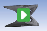
Two views of the solved topology optimization for the torque arm, after the ANSYS software removed all the material it deemed unnecessary to meet the load and stress demands on the part.
The solved model that emerged is an organic shape that represents how the load moves through the torque arm. In contrast to the original human-designed part, the optimized torque arm is not symmetrical. It resembles an I-beam, but with tapered flanges and a central rib that curves. This design feature is the software’s response to information gleaned from simulating the full bell crank assembly: The torque arm is subject to uneven pressure in use.
“You don’t get an even distribution of load through the contact surface,” Humrick explains. “You have a lot of edge contact along the inner edge, and almost no load transfer at all towards the outer end of the shaft.” The software compensated for this load distribution by removing most of the material on the arm’s outer edge and curving the central rib directly toward the inner edge to provide needed support.
Preparing the Topology Optimized Design for 3D Printing
The solved topology optimization model as it stands is not manufacturable. Further design work — with a human touch this time — was needed to develop this model into a printable part. Humrick exported the model into Siemens NX CAD, and used the optimization as the basis for a more refined design. Each CAD iteration was inserted back into the ANSYS bell-crank assembly simulation for validation.
In the final part design, Humrick smoothed the model’s edges and added extra material to the interface surfaces to facilitate machining. He also removed additional material from the curved web by incorporating a truss structure, reducing both support structure material and overall weight.
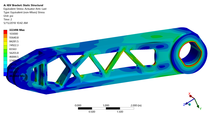
ANSYS predicted the uneven pressure between the two contact points of the torque arm during the topology optimization process. Humrick’s design, shown here in structural analysis, incorporates this insight into a design with an asymmetric web structure that curves to meet the pressure.
Further changes were necessary to take the CAD file to a printer-ready file, including selecting the print orientation and incorporating a flat edge on one side of the part to make it easy to print via powder bed fusion and cut from the build plate. The final design incorporates elements of both the simulation-informed topology optimization and human decisions about manufacturability. The 3D printable part matches the stiffness of the original torque arm, but with a 45% weight reduction.
“If you were to optimize this based on hand calculations, you probably end up with a symmetrical I-beam, whereas using the optimization software, you get an I-beam, but with a very unsymmetrical design,” Humrick says. “That was a kind of nonintuitive result that I think highlights the benefits of using topology optimization, not just to minimize the weight of existing designs, but as more of a creative tool.”

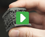
These half-scale ABS models were 3D printed by Phoenix Analysis & Design Technologies (PADT) to show the difference between the original torque arm and the topology optimized version. The actual replacement part will be 3D printed in 17-4 stainless steel via powder bed fusion. Photo: PADT
I discussed this application in more detail with Humrick and Pam Waterman, 3D printing applications engineer for Phoenix Analysis & Design Technologies (PADT), an ANSYS reseller and frequent collaborator with Advatech. To learn more about the topology optimization process, see the video below:
Related resources:
Related Content
DMG MORI: Build Plate “Pucks” Cut Postprocessing Time by 80%
For spinal implants and other small 3D printed parts made through laser powder bed fusion, separate clampable units resting within the build plate provide for easy transfer to a CNC lathe.
Read MoreAdditive Manufacturing Is Subtractive, Too: How CNC Machining Integrates With AM (Includes Video)
For Keselowski Advanced Manufacturing, succeeding with laser powder bed fusion as a production process means developing a machine shop that is responsive to, and moves at the pacing of, metal 3D printing.
Read MoreActivArmor Casts and Splints Are Shifting to Point-of-Care 3D Printing
ActivArmor offers individualized, 3D printed casts and splints for various diagnoses. The company is in the process of shifting to point-of-care printing and aims to promote positive healing outcomes and improved hygienics with customized support devices.
Read MoreWith Electrochemical Additive Manufacturing (ECAM), Cooling Technology Is Advancing by Degrees
San Diego-based Fabric8Labs is applying electroplating chemistries and DLP-style machines to 3D print cold plates for the semiconductor industry in pure copper. These complex geometries combined with the rise of liquid cooling systems promise significant improvements for thermal management.
Read MoreRead Next
Video: 3 Roles for Simulation in Additive Manufacturing
This conversation with PADT’s Eric Miller explores how simulation and 3D printing work together at three distinct stages in additive manufacturing, for DFAM and beyond.
Read MoreVideo: Topology Optimization versus Generative Design
Why do these strategies matter in design for additive manufacturing (DFAM), and what’s the difference? A conversation with PADT’s Eric Miller explores AM and design, including its human element.
Read MoreHow Topology Optimization Could Be the Key to Longer-Lasting Hip Implants
Hip stem implants must support the mechanical loads of the patient’s lifestyle, but should also avoid stress shielding. A team from Altair leveraged simulation, topology optimization and 3D printing to design an optimized hip stem that meets both conditions.
Read More
.jpg;width=70;height=70;mode=crop)
