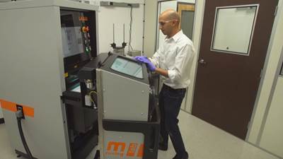
Video: 3 Roles for Simulation in Additive Manufacturing
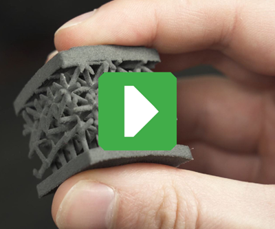
This conversation with PADT’s Eric Miller explores how simulation and 3D printing work together at three distinct stages in additive manufacturing, for DFAM and beyond.
Additive manufacturing (AM) can be a risky business. The beautiful, intricate design that looked great in the CAD program might print out of spec, crash the printer or even fail in use. How can AM users ensure that parts print and perform as expected?
At Phoenix Analysis, Design & Testing (PADT), simulation is the key. I recently spoke with Eric Miller, PADT cofounder and principal, about the various roles that simulation plays for his company’s 3D printing business. Watch the video below or read on for a transcript of our conversation.
(Want to learn more about simulation specifically in DFAM? See the portion of our conversation that explores topology optimization and generative design here.)
Transcript
Stephanie Hendrixson, Additive Manufacturing
I'm Stephanie Hendrixson with Additive Manufacturing Media. I'm here with Eric Miller from PADT. Eric, describe PADT. How does additive manufacturing play into your business?
Eric Miller, Phoenix Analysis, Design & Testing (PADT)
We started the company back 25 years ago because we were using 3D printing, advanced CAD and then simulation, and combining all those three together was kind of the whole point of the company. Simulation has been a very important part of the foundation of everything we do.
Stephanie Hendrixson
In terms of additive manufacturing, you see simulation playing a couple of different and really important roles. What are those?
Eric Miller
The first one which is really exciting is this whole idea of optimizing the design from a shape and weight and additive standpoint. We like to call that generative design, and topological optimization is a subset of that. So we basically take the part and put loads on it and say “remove material where you can” to make it as light as possible and still meet our requirements.
And the second thing that we do is make sure the parts can work. So you've done all this work designing it, making sure it's right. Is it going to break? Is it going to get too hot? Is it going to vibrate? It's not just physical stress and vibration. It's also fluid flow. It's also electromagnetics. So we use simulation in a multiphysics way to do the whole part, make sure it's going to work in the field and give the performance that the customer wants, and optimize that performance as well.
And the third way we're using it is to model the process itself.
Stephanie Hendrixson
In terms of part design verification, what are some of the potential problems that you might discover in that stage and then what do you do to solve those problems?
Eric Miller
Well the biggest that we see is that you've optimized your part for the manufacturing process or using a tool like generative design for a certain loadcase, and you've got another loadcase that's going to cause a part to fail.
A good example that is a lot of these parts we're seeing that come out of simulation have these like really skinny, kind of organic-looking long spars in them which are really cool. It removes a lot of weight. But what if you get a resonant frequency at the same resonant frequency of that spar? You put it on a car and the car vibrates at, say, 240 Hertz. It's going to vibrate and fail and then the part is going to fail.
Or buckling. A lot of times we're doing loads for the standard cases, the worst cases, but we design these kind of spindly parts that are going to buckle if we put a compressive load on them. You've got to look at the whole load history, the whole mission profile of your part.
Stephanie Hendrixson
So you've optimized your design. You verified your design. Now you have to simulate the build. What are the things that can go wrong there, and what do you do about it?
Eric Miller
During the build what we really worry about is the part breaking away from the supports, sticking up, hitting the blade and causing a crash. That's the biggest thing we want to avoid and it unfortunately is quite common.
The other problem is when we take it out and we do our heat treat and we remove it from the base, it may still distort quite a bit. And how much of the distortion is there relative to the part that I really want from CAD? So we can predict that, and not only can we predict it, most of the tools allow us to subtract that off the original geometry so we compensate for it, so when it's done we can actually get the part in the shape we want.
These tools are really coming along in the last couple of years and I think people that are employing them are cutting down their iterations. Even if your part doesn't crash, you’ve still got to scan it, find out where it's wrong, go fix the design. Why are we doing that manually? We could be doing that on the computer in a couple of days rather than using a machine.
Stephanie Hendrixson
Right. So just in the same way that additive is kind of compressing the supply chain, and you're manufacturing kind of all in this one box, we could be doing our design verification and iteration in software.
Eric Miller
That's exactly right. Virtual prototyping. What additive allows us to do as design engineers is be very creative. It's the freedom to create parts without being constrained by traditional manufacturing.
What simulation allows me to do is experiment in a virtual environment to really be creative as well. So without going out and building and testing, I can try these crazy things that I would've never done before. Like what if I do put conformal cooling in there? I've never been able to do that before. Let's try it. Throw some passages in there, run some fluid with it, do a heat transfer analysis. That's a couple hours’ worth of work to just get a first passed answer on it, and I can tell whether it's going to help or not. So I can really be free to explore and take more risk because I can check it very easily.
Stephanie Hendrixson
So it's time savings, it's creativity. But it's also just being able to make better parts and to know that they're better.
Eric Miller
Yeah, know they’re better before you get out there. Yeah.
Related Content
Robot Vs. Gantry for Large-Format Additive Manufacturing (Includes Video)
Additive Engineering Solutions, specialist at 3D printing very large parts and tools on gantry machines, now also uses a robot for large-format AM. Here is how the robot compares.
Read MoreDecentralized Manufacturing Network Aims to Make 3D Printers a Shared Global Resource
The 3DOS additive manufacturing network will let OEMs and creators take advantage of open 3D printer capacity anywhere in the world.
Read MoreSemiconductors, Tungsten, AM Affordability and More from Formnext 2024: AM Radio #56
The trade show included increased applications for the semiconductor market, machine launches and technology advances aimed at cost cutting, plenty of LFAM and more. Listen to our conversation on Formnext 2024.
Read MoreCopper, New Metal Printing Processes, Upgrades Based on Software and More from Formnext 2023: AM Radio #46
Formnext 2023 showed that additive manufacturing may be maturing, but it is certainly not stagnant. In this episode, we dive into observations around technology enhancements, new processes and materials, robots, sustainability and more trends from the show.
Read MoreRead Next
Video: Topology Optimization versus Generative Design
Why do these strategies matter in design for additive manufacturing (DFAM), and what’s the difference? A conversation with PADT’s Eric Miller explores AM and design, including its human element.
Read MoreSeries: Installing a Metal 3D Printer
A five-part series documents one manufacturer’s experience and lessons learned while installing a powder-bed fusion metal 3D printer.
Read MoreBike Manufacturer Uses Additive Manufacturing to Create Lighter, More Complex, Customized Parts
Titanium bike frame manufacturer Hanglun Technology mixes precision casting with 3D printing to create bikes that offer increased speed and reduced turbulence during long-distance rides, offering a smoother, faster and more efficient cycling experience.
Read More
.jpg;width=70;height=70;mode=crop)
