Your Metal AM Process Development Tool? A Spreadsheet (Includes Video)
Spreadsheet integration with Renishaw software allows for fast programming of metal additive manufacturing test builds. Watch video for demonstration of defining many laser parameter combinations for use in a single test.
Metal additive manufacturing — specifically laser powder bed fusion (PBF) — routinely requires trial-and-error. For a new alloy used in this laser-based process, different laser parameters including power, spot diameter, speed and the distance between adjacent paths all interrelate with the chemistry and composition of the material to such an extent that the parameters delivering the best and most consistent part properties likely cannot be predicted. They have to be found experimentally. And the same is true for a new shape made additively. The geometries of part features and supports interrelate with the parameters used to form them so that only certain combinations of settings are likely to produce the part well. AM process development therefore needs test builds, and the fastest way to do this process development is with builds that systematically test many parameter sets all at once. That is, builds consisting of an array of geometrically identical parts for running build parameter trials in parallel.
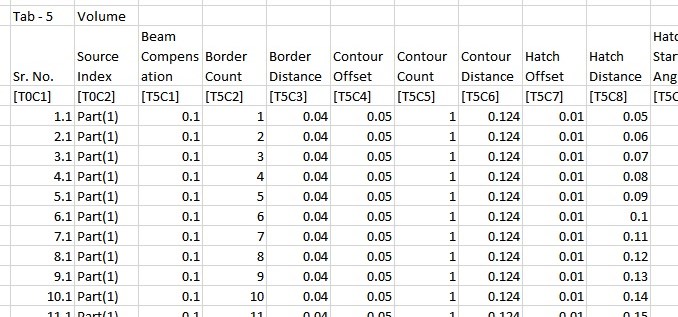
"Border Count" on this spreadsheet is a value that determines how much of the volume of the metal parts is shaped by the laser tracing the shape of the part's border, and therefore how much of the volume is left on the inside for the laser to form through parallel hatching paths. This image is just a detail of a Microsoft Excel spreadsheet that accounts for more than 100 parameters of the build.
Metal additive manufacturing software from Renishaw now offers a simple feature that is powerful for this kind of testing. The company’s software for laser PBF is QuantAM, a tool for taking a CAD model all the way through steps such as build orientation and slicing to production on a Renishaw machine. The simple feature is this: comma-separated values (CSV) data importing — meaning data importing in the format of a spreadsheet such as Excel. With this feature, a user can construct all the different parameter sets for all the different test pieces in an additive build using just a spreadsheet, then allow this spreadsheet to define the build program for the machine.
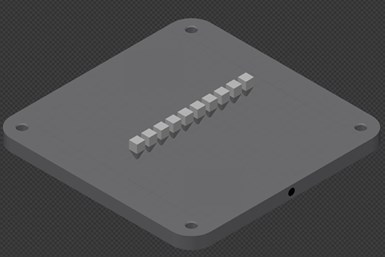
Test cubes such as those in the array seen here are often used to discover the optimal set of 3D printing properties for a new metal alloy, or for an alloy being applied for the first time on a new machine. The spreadsheet functionality makes it easy to quickly define the parameter sets for a designed experiment using these cubes, or even an array of many more cubes than this in a single build.
Renishaw additive manufacturing engineer Kevin Brigden points to the common case of bulk density test cubes used to evaluate the 3D printing of a new AM alloy. The cubes are small enough that a 10-by-10 array of them might be run in a single build — 100 cubes, each with a different combination of properties. Using a spreadsheet, it is an easy matter to populate these parameters across parts 1 through 100, Brigden notes. For example: Increasing laser power by an increment of 10 watts from one cube to the next to the next is an assignment that can be set with a formula.
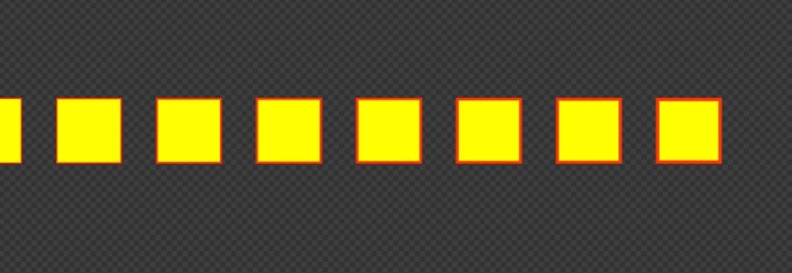
Here is how an incremental change in "Border Count," as seen above, plays out across this row of test cubes. Each cube has one more laser scan path around the border than the one before it. This can be seen in the way the red volume around the border gets progressively thicker from cube to cube. Most build parameter changes don’t have a visible effect within the software in this way. Border Count is a useful parameter to use as a demonstration because it directly changes the scan path.
The same method can even be used to inform different paths for the laser from part to part. On a test cube, the number of boundary laser passes that follow the square outline of the cube versus the number and spacing of hatching passes that create the rest of the inner volume together affect the final properties. On a new part shape being evaluated, these choices related to boundary and hatching passes can aid in realizing the optimum combination of surface characteristics, internal consistency, geometric accuracy and build speed. In a test array of either cubes or parts, the spreadsheet can be used to construct a test of this combination by, say, incrementally increasing the number of boundary layer passes for 10 parts in a row from a single pass up to 10 passes, creating an increasingly thick boundary layer from one part to the next.
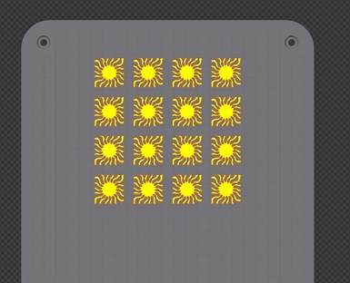
The same spreadsheet methodology could also be applied to finding the best parameter set for accurately producing a new part geometry. Seen here is the view from above an experimental array used to find the build parameters for a 3D printed metal heat-sink component.
Brigden sees even greater potential to come. “Because we are using a spreadsheet interface, it means the data input can be more automated,” he says. “I would expect to see elements of machine learning and AI forming future inputs to this. I could see scenarios where process monitoring outputs could come back around to inform the build.” Truly closed-loop programming is far off, he says, but a “semi-closed-loop” process in which users adjust parameters based on process measurements would be straightforward to implement, simply using the right spreadsheet design.
Brigden and I filmed a conversation about the spreadsheet capability. Learn more about using CSV data to define the build in this video:
Related resources:
Related Content
7 Things We Saw at Formnext 2024 — Video Playlist
There were countless processes, applications and announcements at Formnext 2024. Here are seven standouts Peter Zelinski and Stephanie Hendrixson caught on film.
Read MoreThe Top 10 Additive Manufacturing Stories of 2024
Defense, space exploration, thermal management — these are some of the topics that captured the Additive Manufacturing audience’s interest in 2024. But there’s also an overarching theme: Don't wait for additive manufacturing to be perfect. Instead, leverage the applications perfect for AM.
Read MoreOvercoming the Bottleneck to Customized Manufacturing: Quoting
Spokbee’s software-as-a-service platform is shaving months off of the quoting and pricing process for 3D printed and other types of configurable products.
Read MoreSpherene Creates Metamaterial with Geometry Derived from Spheres
An algorithm developed by Spherene Inc. generates Adaptive Density Minimal Surfaces (ADMS) as a self-supporting infill strategy that can be used to reduce mass and manage material properties in 3D printed parts.
Read MoreRead Next
Video: Support Structures Are Misnamed! How to Understand Anchors in Additive Manufacturing
Supports or anchors can account for a significant share of both the engineering investment and material use in metal additive manufacturing. Michael Hansen of SLM Solutions discusses the role and importance of support structures.
Read MoreHow Machine Learning Is Moving AM Beyond Trial and Error
A Colorado alliance has found the link between AM and AI. Using machine learning to map the formula for successful metal 3D printing, researchers aim to know the right parameters for any new part with few or no test builds.
Read MoreA $1.5 Million Dive into the Melt Pool
A new, customized digital radiology vault and specialized additive manufacturing system at Auburn University aims to understand and control the complex heat and mass transport phenomena taking place during the laser sintering process.
Read More

