Collaboration Develops Image-Based Workflow for 3D-Printed Part Validation
A team from Synopsys, North Star Imaging and ANSYS developed a process using 3D imaging, processing and CAE to examine the performance of as-manufactured components.
Additive manufacturing (AM) is becoming more widely used by manufacturers, but validating 3D-printed parts remains a challenge. Manufacturers need to not only understand deviations from original designs, but also how parts will perform in use.
A project completed by Synopsys, North Star Imaging (NSI) and ANSYS combined computed tomography (CT) with finite element (FE) simulation to check the suitability of AM parts for their intended design purpose. The workflow this team established uses CT scanning to inspect parts and analyze their deviation from CAD designs; the image models can then be used in FE simulation to determine part performance. Results can be fed into new design iterations prior to manufacturing, and/or used to determine whether the existing part is suitable for its anticipated use.
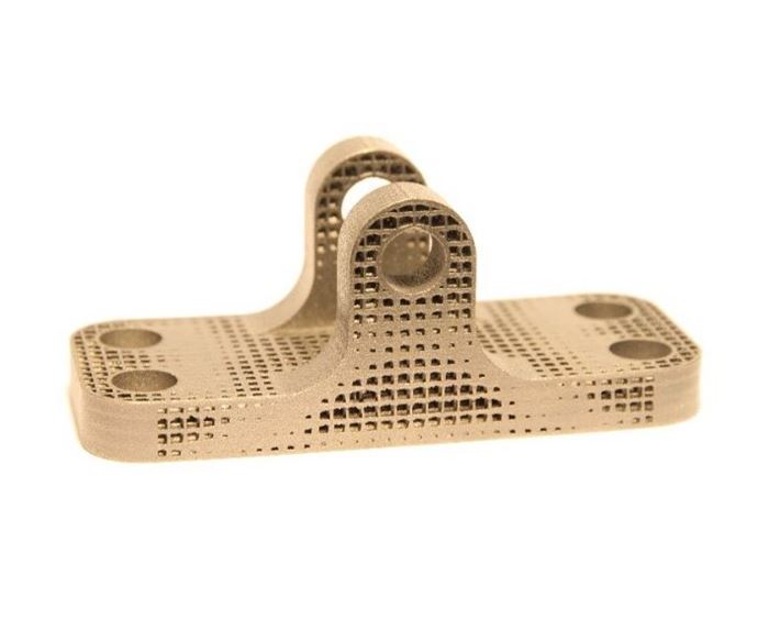
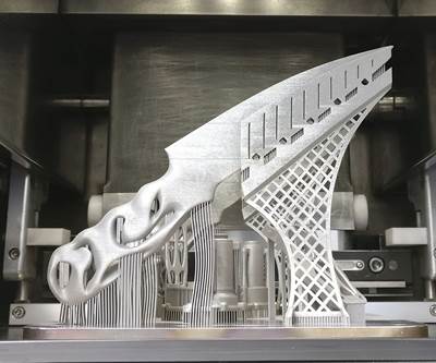
One example of this process involves a bracket geometry designed by a team from the University of Pittsburgh, led by Dr. Albert To. The team used CAD tools to create a proof-of-concept bracket with lattice structures included to reduce weight (Figure 1). ANSYS was used for lattice generation and design validation on a homogenized model before 3D printing on an EOS direct metal laser sintering (DMLS) machine in Ti6AI4V titanium alloy. The University of Pittsburgh worked with Synopsys, NSI and ANSYS to analyze the 3D-printed parts.
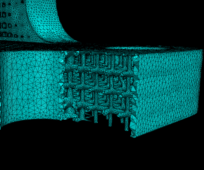
The AM brackets were first scanned at NSI’s lab in Minnesota, creating a dataset suitable for processing. The scan data was then imported to Synopsys Simpleware software for segmentation, processing and generation of high-quality surface and volume meshes (Figure 2). The image-to-mesh workflow with Simpleware software produces meshes that are said to be ready for use in FE solvers without the need for time-consuming repairs and re-meshing.
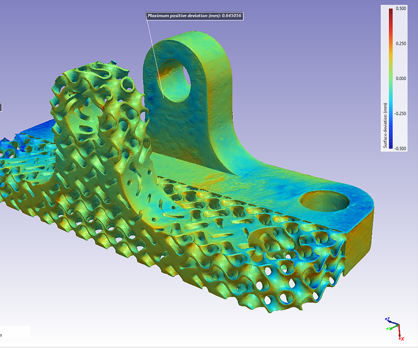
The team compared the image-based STL model with the original CAD data in Simpleware software. Landmark and automatic registration tools, as well as a surface deviation analysis tool, showed that the AM parts differed from the original design in certain ways due to errors caused by the additive manufacturing process (Figure 3).
The volume mesh from Simpleware software was used in ANSYS Mechanical to carry out simulations using the CAD and image-based models. Structural simulation enabled the team to solve mechanical loading problems and evaluate the performance of the as-manufactured part against original design intentions. Results demonstrated that, while differences had occurred between design and AM, the component still met testing requirements.
Following these tests, the image-based workflow was applied to a project being carried out by Moog Inc., involving an impulse pressure manifold manufactured on a Renishaw AM250 laser-powder-bed-fusion (LPBF) machine. Inspection and surface deviation analysis showed manufacturing errors and geometric deviations in the 3D-printed manifold, including issues such as porosity. Moog was able to simulate maximum principal stress in ANSYS Mechanical, and use this information to re-asses the usability of the part. The results showed a 23.18 percent increase in maximum principal stress between the CAD and image-based model of the printed part.
According to the team involved, the short-term value of this inspection workflow is to integrate the various stages of additive manufacturing (including CAD, 3D imaging, 3D printing, image processing and FE simulation) to improve efficiency and repeatability. More broadly, however, this image-based simulation workflow can be used to assess the effect of deviations between as-designed and as-manufactured parts, potentially saving the cost of repairing future manufacturing errors. Adding this insight to design decisions is expected to increase confidence in using optimized AM parts for different applications.
Related Content
7 Things We Saw at Formnext 2024 — Video Playlist
There were countless processes, applications and announcements at Formnext 2024. Here are seven standouts Peter Zelinski and Stephanie Hendrixson caught on film.
Read MoreCopper, New Metal Printing Processes, Upgrades Based on Software and More from Formnext 2023: AM Radio #46
Formnext 2023 showed that additive manufacturing may be maturing, but it is certainly not stagnant. In this episode, we dive into observations around technology enhancements, new processes and materials, robots, sustainability and more trends from the show.
Read MoreSpherene Creates Metamaterial with Geometry Derived from Spheres
An algorithm developed by Spherene Inc. generates Adaptive Density Minimal Surfaces (ADMS) as a self-supporting infill strategy that can be used to reduce mass and manage material properties in 3D printed parts.
Read More3D Printed "Evolved Structures" for NASA Exoplanet Balloon Mission: The Cool Parts Show #61
Generative design creates stiff, lightweight brackets for EXCITE mission monitoring planets orbiting other stars. The Cool Parts Show visits Goddard Space Flight Center.
Read MoreRead Next
Lattices in Footprint 3D Midsoles to Provide Custom Fit
The footwear company plans to offer shoes with custom 3D-printed midsoles using lattices for precise support and cushioning.
Read MoreSimulation Supports Custom 3D-Printed Knife
Build simulation revealed that distortion was likely to occur in this custom chef’s knife. Thermal shrouding and an unusual support structure were used to counter it.
Read MoreProfilometry-Based Indentation Plastometry (PIP) as an Alternative to Standard Tensile Testing
UK-based Plastometrex offers a benchtop testing device utilizing PIP to quickly and easily analyze the yield strength, tensile strength and uniform elongation of samples and even printed parts. The solution is particularly useful for additive manufacturing.
Read More
.jpg;width=70;height=70;mode=crop)
