The Link Between 3D Printing, Surface Finish and Mold Tools
Surface finish for 3D printed mold tooling has a direct effect on the pull-out force needed to remove the final part. Why molders should consider tool roughness along with geometry and materials.
Surface finish is an often overlooked quality of 3D printed injection mold tools. Compared to machined metal injection mold tools, 3D printed tooling appears rougher as different aspects of the 3D printing process (layering, pixelation, etc.) introduce artifacts that increase the surface roughness of the printed parts. Surface finish is a key quality to evaluate when utilizing 3D printed injection mold tools, as a high surface finish will not only make the molded parts more aesthetically pleasing, but it will also prolong the life of the features in the printed tool.
Surface Roughness in Additive Manufacturing
There are a variety of techniques used to measure surface finish. The most common method is to use a standard profilometer, which features a highly sensitive probe that “drags” along the surface of the printed part, logging changes in probe displacement. Using this technique, the experimenter can measure representative surfaces in the tool to gather meaningful information. The Ra value is the average surface roughness of the tested specimen across the entire drag length of the profilometer probe. The examples below use the Ra value to assess the surface quality of 3D printed tooling.
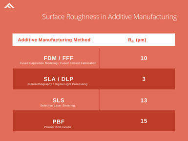
Figure 1. Surface roughness of different AM processes. Image Credits: 3DFortify
The table in Figure 1 demonstrates how the average surface roughness of a printed part is greatly influenced by the additive manufacturing (AM) process. While parts 3D printed with stereolithography/digital light processing (SLA/DLP) exhibit the best-in-class surface roughness, processes such as fused deposition modeling (FDM) and metal additive manufacturing pose challenges for 3D printed tooling and often require additional post-machining work to serve as a satisfactory 3D printed injection mold tool.
There are many methods available to address and improve surface finish through using both 3D printer process optimization and postprocessing techniques. The most common method is to orient the printed part so that the plane with the best surface finish (lowest Ra value) is parallel to the pull direction of the tool. Other processing methods include using shorter layer heights (easily implemented in most 3D printers) or printing at a higher resolution (for DLP-based methods). Lastly, many 3D printing and rapid prototyping service bureaus excel in various methods of postprocessing for improving surface finish, such as bead blasting, and polishing.
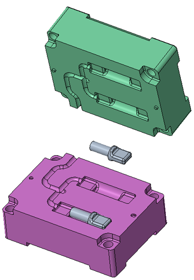
Figure 2. CAD of the 3D printed mold and inserts.
Putting the Molds to the Test
Understanding what surface finish is and how it is measured is critical for the success of 3D printed injection mold tooling applications. To establish the link between surface roughness and better molding outcomes, Fortify engineers designed a test geometry (right) to assess both the surface roughness of a given 3D printed part, as well as the pull-out force (POF) of various molded plastics.
This geometry was printed on a Flux One printer at Fortify’s in-house printing lab. These printers are powered by a DLP light engine and have improved surface quality compared to other 3D printed processes.
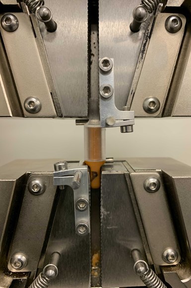
Figure 3. Test specimen set up in the Instron to measure POF.
This test geometry acts as an over-molded insert that sits within a large 3D printed injection mold block. The insert is subjected to a single shot of injection molded thermoplastic, which fully engulfs the cylindrical section of the insert, creating an overmolded section and a tab which mirrors the 3D printed insert. The insert and over-molded plastic are neatly ejected out of the tool for measurement. The 3D printed tab and the molded tab are clipped to the specimen holder of a standard tensile tester (Instron; pictured).
The tensile tester then pulls at both tabs, logging the force needed to remove the molded plastic from the 3D printed insert, which is what Fortify refers to as the pull-out-force (POF). Using this experimental method, surface roughness and POF of various 3D printed materials and injection molded plastics were quickly screened.
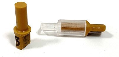
Figure 4. 3D printed insert and overmolded part.
As exhibited in the plot below (Figure 5), there is a strong correlation between the surface roughness and the max POF that the insert was subjected to. The experiments demonstrate that by improving the surface finish of a 3D printed part from around 4 micrometers to under 1.5 micrometers, POF is drastically improved by a factor of 5.
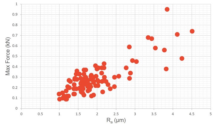
Figure 5. Surface roughness and pull-out force.
Using this method, we can also examine how the type of plastic injected into our test mold affects the POF. The experiments show that, given the same exact surface roughness, different plastics exhibit drastically different POFs.
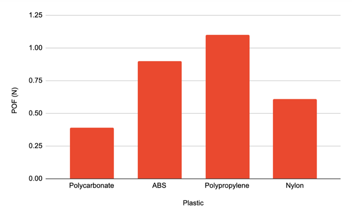
Figure 6. Pull-out force of different molded materials
The last step is to link all this data to practical implications of surface finish and pull-out-force in an actual injection molded application. The Fortify team utilized a mold geometry used for R&D featuring an array of common molding geometries, such as thin walls, standing posts and shut-offs. The features are also varied in difficulty through the use of discrete draft angles, radii and shut-off angles.
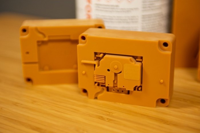
Figure 7. 3D printed tool that features many geometries including angles, radii and shut-off angles.
Intuitively, it makes sense that one would want to reduce the POF of an injected plastic from a 3D printed mold tool. A high POF, or equivalently, a high adhesion force of the plastic to the tool, will result in an increase in the stress on the 3D printed tool both as the mold halves open and during ejection. A high adhesion force, over the course of a handful of shots, can greatly weaken various features of the 3D printed tool, such as standing male extrusions or thin-wall fins.
The chart below (Figure 8) displays a strong correlation between the POF (and thus, the surface roughness) to positive injection molding outcomes. Over the course of 60 full shots, the tool with the lowest surface finish exhibited zero feature failures, while the tool with the worst surface finish exhibited 12 feature failures. Lowering the surface roughness of a 3D printed mold can drastically reduce the number of feature failures, prolonging the life of the tool.
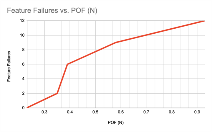
Figure 8. Number of feature failures on the 3D printed tool dependent on POF.
The latest advancements in additive manufacturing technology allow molders to take advantage of the time and cost savings that 3D printed tools can offer. Understanding how surface roughness affects the pull-out force of molded materials will set molders up for success with these tools by choosing the correct AM technique, processing methods and postprocessing for the best surface quality.
About the Author
Karlo Delos Reyes, VP of Applications and Cofounder
A chemical engineer by training, Karlo Delos Reyes runs Fortify’s applications team. Karlo joined the founding Fortify team during his Ph.D. program while serving as president of Origin, a program dedicated to spinning out graduate research into commercial ventures. He holds a dual bachelor’s degree in chemical engineering and biochemistry and cellular biology from the University of California, San Diego. Previously, he worked at the Genomics Institute of the Novartis Research Foundation in its Advanced Automation and Robotics Department.
Related Content
New Zeda Additive Manufacturing Factory in Ohio Will Serve Medical, Military and Aerospace Production
Site providing laser powder bed fusion as well as machining and other postprocessing will open in late 2023, and will employ over 100. Chief technology officer Greg Morris sees economic and personnel advantages of serving different markets from a single AM facility.
Read MorePostprocessing Steps and Costs for Metal 3D Printing
When your metal part is done 3D printing, you just pull it out of the machine and start using it, right? Not exactly.
Read More8 Cool Parts From Formnext 2023: The Cool Parts Show #65
New additive manufacturing technologies on display at Formnext were in many cases producing notable end-use components. Here are some of the coolest parts we found at this year’s show.
Read More3D Printed Cutting Tool for Large Transmission Part: The Cool Parts Show Bonus
A boring tool that was once 30 kg challenged the performance of the machining center using it. The replacement tool is 11.5 kg, and more efficient as well, thanks to generative design.
Read MoreRead Next
3D-Printed Molds Accelerate Substitute-Ventilator Validation
Fortify’s 3D printing and injection molding expertise saved Ventilator Project weeks and thousands of dollars as the nonprofit hurried to supply clinicians and hospitals at the start of the COVID-19 pandemic.
Read MorePVD Coatings Solve Common 3D-Printed Mold and Part Problems
The right surface modification solution can alleviate a few common additive manufacturing pain points that typically require creating new molds or parts.
Read MoreReinforced Polymer 3D Printing, Adjustable on the Fly
With Continuous Kinetic Mixing (CKM), 3DFortify sees expanded possibilities for printing polymer composites reinforced with fibers, ceramics and even metal flake in any concentration needed.
Read More
