What Effect Does Gas Flow Have in Metal Additive Manufacturing?
Sintavia has partnered with one of the world’s leading providers of industrial gases in order to understand and improve metal AM’s most significant process variable.
Of all the process parameters in metal additive manufacturing, none may be as consequential and complex as gas flow dynamics. Inert gas, typically argon, is central to the function of metal additive machines, as well as peripheral AM processes such as hot isostatic pressing (HIP-ing), and is the media most often used for quenching during the vacuum heat-treating process.
Sintavia, a tier-one metal additive manufacturing company founded in 2016 by Brian Neff and partner Doug Hedges in Davie, Florida, is so invested in understanding gas flow dynamics that the company recently partnered with Taiyo Nippon Sanso Corporation (TNSC), one of the world’s leading providers of industrial gases. Based in Tokyo, Japan, TNSC has extensive experience researching and providing proprietary gas flow solutions for industrial welding applications. The partnership aligns with Sintavia’s lab-testing-first philosophy toward metal AM processes. In fact, while the company today is focused on scaled AM production, Neff and Hedges didn’t purchase their first additive machine until their lab had conducted tests across metallurgy, metrology, heat treating, mechanical testing, CAD and designing for additive.
To understand the impact that gas flow dynamics have on a typical powder-bed fusion build, I visited Sintavia this March and got a first-hand look at a recent test build. Hedges, the company’s president, walked me through the process with one of the company’s lab technicians.
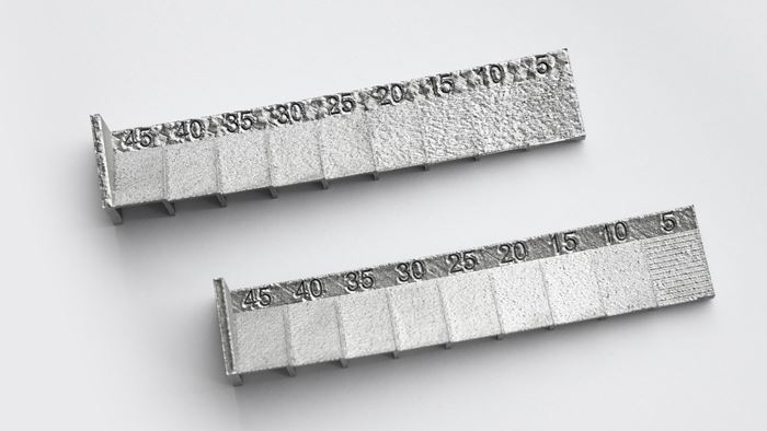
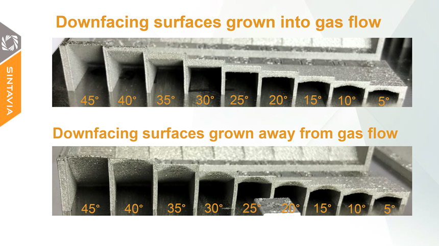
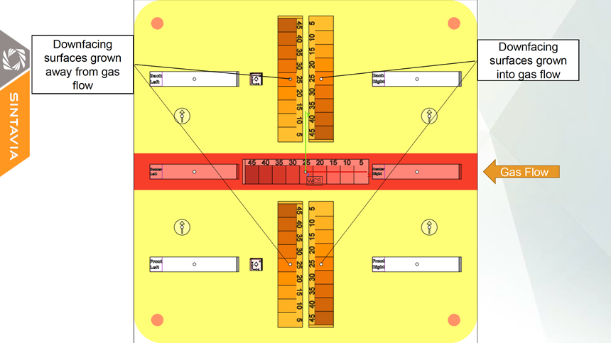
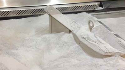
The first image above shows two test pieces grown to show the effects of gas flow on down-facing surfaces. In the machine used for this test, argon gas entered from the right-hand side of the chamber. The argon was slightly over-pressured for the test, running at 12 millibars and flowing at 9.5 meters per second into the chamber in order to keep the oxygen levels at a low extreme. The piece shown on the bottom was grown facing the gas flow, while the piece on the top was grown facing away from it. The pieces themselves were designed with no supports and included multiple feature angles.
A close look at the two pieces reveals clear disparities. The overall geometry of the bottom piece is cleaner and closer to the CAD model than the top. A rounding effect can be seen on the top piece, especially at the edges along its top border, which also appear to be thinner. The surface finish of the bottom piece is also smoother, and the piece lacks the slight discoloration that is noticeable on the top piece.
Of course, the orientation of the part in relation to gas flow direction is not the only variable that affects these disparities within a build. Multiple parameters and components within the chamber interact with and influence the gas flow, including the rate of that flow, the speed created by the vacuum pump, the position of the recoater blade, and operational variabilities across the machines themselves.
In the meantime, as the laser hits the powder, particles (including nanoparticles) shoot out of the melt pools and are caught in the argon stream. Ideally, the gas carries this spatter across the powder bed and into the vacuum where it’s trapped inside the machine’s filters. But this is not always the case.
To understand how the recoater blade influences the argon flow, imagine dropping a boulder into a rapidly flowing creek. As the boulder forces the water to flow around it, areas immediately surrounding the rock experience differing degrees of turbulence. Moving the boulder along the stream’s path may affect the direction and force of this turbulence as the water’s path is reoriented around the rock. Recoater blades have a similar effect on the flow of gas inside a build chamber. On a dual-direction recoater, the blade moves forward, stops, exposes the layer and moves back. At each point in this process, the argon is reorienting its path around the blade and affecting the flow dynamics of the argon.
In the meantime, as the laser hits the powder, particles (including nanoparticles) shoot out of the melt pools and are caught in the argon stream. Ideally, the gas carries this spatter across the powder bed and into the vacuum where it’s trapped inside the machine’s filters. But this is not always the case. The longer the exposure time for each layer, the more the nanoparticles and soot build up within the chamber and increase the risk of interfering with the laser intensity. Multiply this contaminant effect over time, and the process degrades the longer it continues.
To illustrate this phenomenon, Sintavia’s machine technician lowers the speed of the vacuum pump as we look inside the active build chamber. As he lowers the speed, turbulences form within the chamber, and the soot that had been flowing steadily from left to right begins to trickle upward toward the laser. Sparks escaping the melt pool are elongated upwards rather than bending in the direction of the gas flow.
If you were to look at a 2D cross-section of a part built from these conditions, you would find larger particles of splatter that landed in a nearby melt pool and were re-exposed to the laser. Since builds can take several weeks, it’s almost always the case that the powder toward the downstream side of the chamber is “browner, different-shaped and different-sized” than the unaffected powder in the bed, Hedges says. “Different machines are better at dealing with this issue.”
Hedges notes that there are numerous adjustments that can be made to keep the chamber environment relatively clean. But some of these adjustments, or “tricks,” such as delaying the recoating time in order to let the argon carry the contaminants out of the chamber, add time to the overall process. “The faster you can get those contaminants out of the chamber, the faster this process is going to mature and gain an adoption for people within industry that want to use it,” he says.
Sintavia CEO Brian Neff says that the partnership with TNSC is not about Sintavia wanting to venture into research and development around gas flow dynamics. It is, he says, strictly meant to demonstrate to both OEMs and customers that there are ways to scale production. “Everything comes down to cost and speed,” Neff says. “Because of what we know about gas flow dynamics, we can make adjustments with our part orientation, the way we design our supports and so on. But even though we have technological leadership to some degree, we're not trying to be a leading edge in R&D. We want to apply this to scale production, to get faster build times at lower costs, period.”Related Content
Endeavor 3D Earns International Traffic in Arms Registration
Endeavor 3D strengthens its technology capabilities and operational systems to better support the U.S. defense industrial base as well as energy and supply chain manufacturing services.
Read MoreBaker Hughes Successfully Implements Oqton Manufacturing OS System to Optimize Additive-Driven Manufacturing Workflow
3D Systems say this successful implementation demonstrates its Oqton Manufacturing OS’ ability to accelerate the design and production of additively manufactured parts across the entire manufacturing workflow to increase efficiency and facilitate regulatory compliance.
Read MoreDOE Awards Nearly $3 Million to Develop Additive Manufacturing of Modular Wind Blades
The industry partners received the award to develop automation in additive manufacturing of tooling for large-scale wind blades that can accommodate continuous changes in blade geometry and scale.
Read More3D Printed Spacer Grids for Nuclear Power: The Cool Parts Show #79
Westinghouse Electric Company is exploring laser powder bed fusion as a means of manufacturing spacer grids, critical parts of the fuel rod assemblies used in pressurized water reactors.
Read MoreRead Next
Crushable Lattices: The Lightweight Structures That Will Protect an Interplanetary Payload
NASA uses laser powder bed fusion plus chemical etching to create the lattice forms engineered to keep Mars rocks safe during a crash landing on Earth.
Read More3D Printed Polymer EOAT Increases Safety of Cobots
Contract manufacturer Anubis 3D applies polymer 3D printing processes to manufacture cobot tooling that is lightweight, smooth and safer for human interaction.
Read MorePostprocessing Steps and Costs for Metal 3D Printing
When your metal part is done 3D printing, you just pull it out of the machine and start using it, right? Not exactly.
Read More

