The Challenge with AM Process Substitution
Understanding the cost curves for AM is key.
I have lost track of how many times I have stressed the economic (and technical) challenges companies face when attempting process substitutions with additive manufacturing (AM), or what I often refer to as “replicating” a part with AM. In short, everyone thinks a metal AM part is going to be cheaper than the machined, cast, or forged version of the part (or be as strong as the injection molded part for those working in plastics) based on all of the hype, only to find that it is not. The “sticker shock” and disappointment that ensues often dampens the enthusiasm for AM and can even undermine future AM investments, creating an uphill battle for AM.
The part in the training example that I discussed last month suffered a similar same fate. It had been identified through a rigorous screening process as a potential candidate for an AM process substitution, using AM part selection criteria similar to what I described previously. Even better, the buy-to-fly ratio for the part was over 9:1 when machined; so, there was a lot of waste that could be eliminated. Plus, the part was made from titanium, an expensive material that can be tough to machine, making it a “high value” target for AM.
Unfortunately, substituting AM for machining to make a 1:1 replacement of this part was not immediately cost effective. The part needed considerable redesign for AM in order to even get in the ballpark, and I showed how that progressed on multiple fronts in the training activity using the cost-per-kg chart.
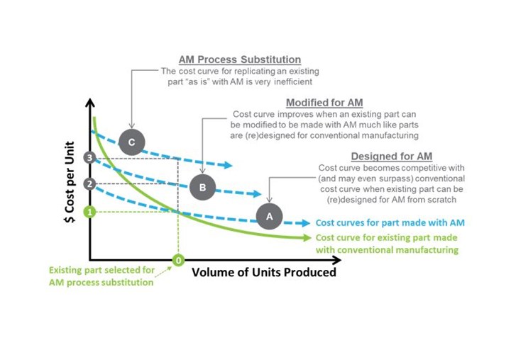
Challenges of AM process substitution illustrated by cost curves for conventional manufacturing and AM, inspired by the work of Martin Leary in Design for Additive Manufacturing textbook. Photo Credit: Timothy W. Simpson
This month’s figure provides an alternate view on that progression, tying it back to the AM cost curves that we often see to try and justify AM. This particular figure is inspired by the cost curves and discussion introduced in the first chapter of Martin Leary’s Design for Additive Manufacturing book — hands down the best explanation of the cost tradeoffs associated with AM technology that I have ever read.
As with most conventional manufacturing processes, the unit cost for the traditionally made part decreases as the production volume increases. This the basis for economies of scale: the more parts one makes, the cheaper they get as Henry Ford showed us over a hundred years ago. As such, all existing parts have been designed to be made as economically as possible for the given manufacturing process(es) based on the quantity needed to satisfy the estimated demand.
Now, when someone selects an existing part made with a conventional manufacturing process, that part was designed (and optimized) to be made on that process based on an associated production quantity, which I have labeled as “0” in the figure. The associated unit cost to make the existing part with the existing manufacturing process is labeled “1”, the line horizontal to where the vertical line originating from “0” intersects this cost curve.
Herein lies the rub. Many assume that because the AM cost curve is flat, it should intersect at (or at least near) this same point, but it does not. Why? Because the existing part has not been designed to be made with AM; it was designed (and optimized) to be made with the more conventional manufacturing process that is currently used to make it. As a result, you are not operating on the curve that I have labeled “A” as you expect. In reality, you are operating on a “less optimal” cost curve for AM when you are trying to replicate an existing part with AM, which I have illustrated by the curve labeled “C” in the figure.
If you continue projecting the line vertically from “0” until you hit the curve labeled “C”, then you arrive at the point labeled “3”, which is the cost for replicating the existing part without any redesign for AM. In my experience, I am actually being generous showing that the unit cost at “3” is roughly double “1”; it is often much, much higher. Nonetheless, you now see yet again why a direct AM process substitution does not yield the results you are often led to believe.
The good news, though, is that modifying and ultimately designing a part for AM can help shift the slope of this cost curve, or better yet, move “down” to a different, less expensive cost curve. If the designer has some freedom to modify the part for AM, or MfAM as many refer to it, then the cost associated with printing and removing support structures, for instance, decreases the material, build, and post-processing costs. This moves you to cost curve “B”, which yields a reduced unit cost that I labeled “2”. Giving designers additional freedom to lightweight the part, for instance, or redesign it to add value in other ways helps reduce the cost further, illustrating how Design for AM (DfAM) is a “value multiplier”.
Interestingly, in my work this past year with John Barnes and The Barnes Global Advisors, he arrived at similar cost curves starting from the design of an entirely new part, not redesign of an existing one as I have done here. We were excited when the two of us compared notes as it confirmed that Martin Leary’s logic behind the AM cost tradeoffs now holds from two other perspectives, giving us more insight into the pathway to profitable AM.
Related Content
Flexible Bellows Made Through Metal 3D Printing: The Cool Parts Show #64
Can laser powder bed fusion create metal parts with controlled flexibility? We explore an example in this episode of The Cool Parts Show.
Read MorePreassembled Turbojet Engine, 3D Printed in One Build: The Cool Parts Show #75
Turbojet engines typically consist of hundreds or thousands of parts, but this engine — 2023 winner of The Cool Parts Showcase for Best Proof of Concept — was 3D printed as just two pieces, with the monolithic rotor embedded inside the stationary engine shell.
Read MoreThis 3D Printed Part Makes IndyCar Racing Safer: The Cool Parts Show #67
The top frame is a newer addition to Indycar vehicles, but one that has dramatically improved the safety of the sport. We look at the original component and its next generation in this episode of The Cool Parts Show.
Read More3D Printed Cutting Tool for Large Transmission Part: The Cool Parts Show Bonus
A boring tool that was once 30 kg challenged the performance of the machining center using it. The replacement tool is 11.5 kg, and more efficient as well, thanks to generative design.
Read MoreRead Next
Alquist 3D Looks Toward a Carbon-Sequestering Future with 3D Printed Infrastructure
The Colorado startup aims to reduce the carbon footprint of new buildings, homes and city infrastructure with robotic 3D printing and a specialized geopolymer material.
Read MoreCrushable Lattices: The Lightweight Structures That Will Protect an Interplanetary Payload
NASA uses laser powder bed fusion plus chemical etching to create the lattice forms engineered to keep Mars rocks safe during a crash landing on Earth.
Read MorePostprocessing Steps and Costs for Metal 3D Printing
When your metal part is done 3D printing, you just pull it out of the machine and start using it, right? Not exactly.
Read More


