New Research Advancing Additive Manufacturing Viability
New research shows that 3D-printed parts are similar to barstock and have high manufacturing repeatability.
Additive manufacturing in the form of direct metal laser sintering (DMLS), also known as direct metal laser melting (DMLM), is an extremely useful alternative to conventional manufacturing techniques. Building parts from metal powder frees designs from many engineering constraints and is often faster and more cost-competitive than machining them out of ingots or castings. But are the parts as good?
Studying variations in build orientation, layer thickness and build chamber atmospheres for 17-4PH stainless steel parts reveals little difference in material properties between 3D-printed and conventionally made metal parts, yet notable increases in DMLS process efficiencies.
Background
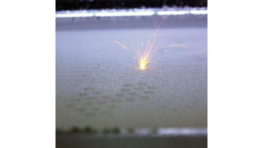
Direct metal laser sintering emerged in 1995 from EOS of Munich, Germany. The process starts by depositing a thin layer of powdered metal onto a build platform with a recoating arm that acts like a rake. Next, a laser precisely melts the metal powder that makes up the part’s geometry for that layer. The laser provides enough energy to bring the metal powder to a liquid state, and it is allowed to re-solidify before the next layer is recoated and welded. These steps repeat sequentially until a complete part emerges. Because the technology uses a “ground-up” building technique, DMLS has the ability to create complex geometries and internal structures impossible for machining or casting.
Many factors go into processing parts through DMLS and little is known about the effect of varying parameters on material properties. The 17-4PH stainless steel grade is a versatile material used in many major industries, so advancing research on this material is extremely important. Previous 17-4PH studies focused on general material properties using standard parameters specified by machine manufacturers. Few studies have been done concentrating on parameter variations such as layer thickness, build atmosphere and build orientation.
This study was conducted to explore the effects that these variations have on material properties. Increased understanding will aid in advancing processing parameters for the material and can therefore be extrapolated for research on other materials.
Material Specs and Characterization
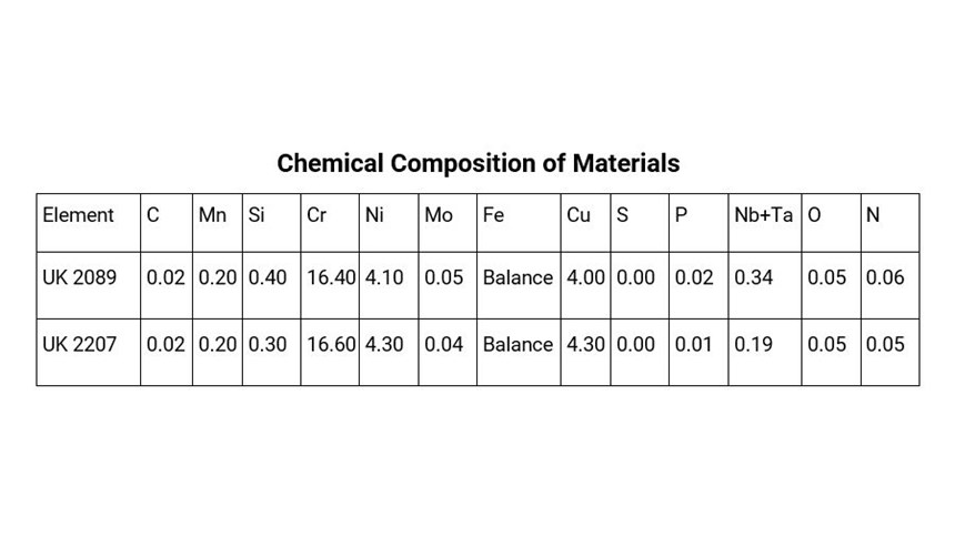
Stainless steel powder for this study was acquired from powder material supplier LPW (Pittsburgh, Pennsylvania) with product specification UK 2089 and UK 2207. (The chemical composition for both materials is given in Table 1 in the slideshow above.) Linear Mold & Engineering (Livonia, Michigan) provided space and equipment for this research. Due to the nature of the DMLM process, the majority of material within the machine during a build can be sieved and reused in later builds. Reclaiming and combining multiple lots of powder is common practice at Linear in order to reduce downtime because of powder quantity limitations. Chemical composition and size characterization of 10 randomized material samples were examined prior to the build.
Experimental Groups and Processing
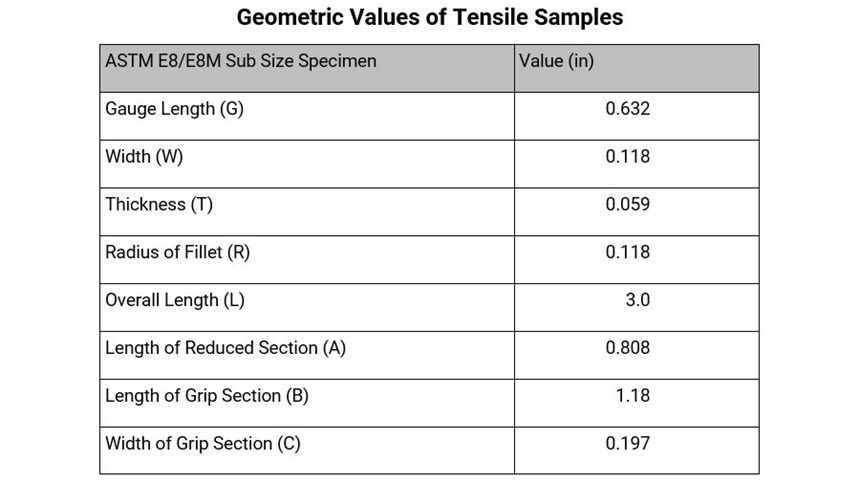
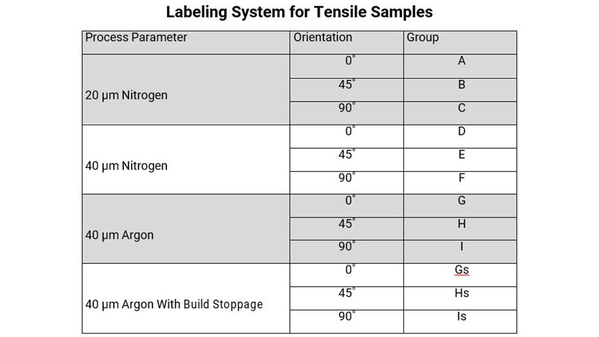
One hundred and twenty reduced-size tensile samples (see Table 2) were built utilizing EOS DMLS technology with four process parameters that represent micron layer (20 or 40 µm) and inert gas atmosphere (nitrogen or argon). For each process parameter, samples were built in one of three orientations relative to the build platform (0°, 45° or 90°). Groups (n=10) for each process parameter and build orientation configuration were built and tested. Each sample was labeled according to group process parameter and build orientation, as shown in Table 3.
Mechanical Testing
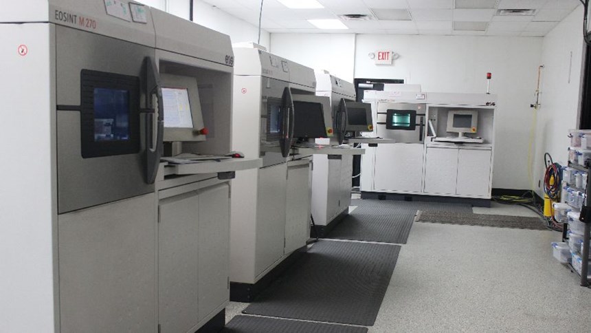
The specimens were built using EOS M270 and EOS M280 direct metal laser sintering machines. They were then stress-relieved at Linear, and solution heat-treated and age-hardened to H900 specifications at Vac-Met (Warren, Michigan), a certified postprocessing company, in order to accurately replicate real-world material applications. A parts list was used to track the parts and record data throughout the experiment.
The parts were tested on Lawrence Technological University’s Instron Electropuls10000 electromechanical testing equipment in combination with a video extensometer to precisely measure load and displacement. Each specimen group was marked with reflective tape and painted to add contrast for proper function of the video extensometer during testing. Values were recorded automatically as well as manually throughout the test. Each subgroup’s data was represented on a single graph to visually relate the consistency of one specimen to the next. The recorded data allowed for accurate calculation of the values in question: ultimate tensile strength (UTS), yield strength (YS) and percent elongation.
Fracture Surface Analysis
Following the mechanical testing, fracture surfaces were analyzed using Lawrence Technological University’s FEI ESEM. Specimen one of each 0˚ and 90˚ group was analyzed in order to determine fracture mechanism in addition to any noticeable irregularities between groups and subgroups.
Results
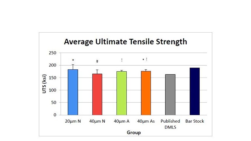
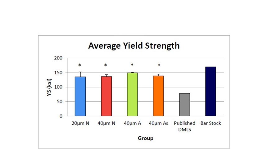
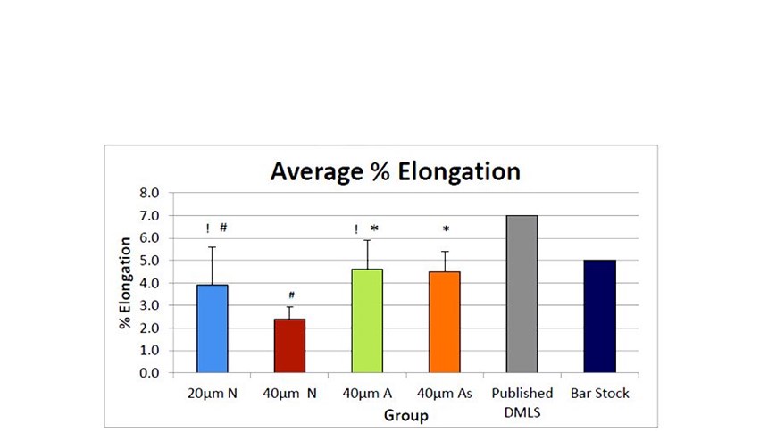
The study results and methods for determining them are detailed below. See Figures 3 through 5 in the slideshow above for additional detail.
Mechanical Testing
Mechanical testing showed results of very low variability between groups and within groups represented as low standard deviations. These values were compared by orientation within groups and between process parameter groups. Mechanical properties were expressed as means ± standard deviation for each group and subgroup. Differences in mechanical properties UTS, YS and percent elongation were determined by two-way analyses of variance (ANOVAs) with Tukey pairwise comparison posttests. Differences with P > 0.005 confidence were reported as significant.
Ultimate tensile strength of all groups showed a slight decrease in magnitude with respect to an increase in build orientation angle. (See Figure 3.) This, however, wasn’t the case in the 20 µm N group where specimens built at 45˚ proved to have the greatest magnitude. Overall, ultimate tensile strength between the 20 µm N, 40 µm A and 40 µm A with build stoppage groups were statistically identical. Ultimate tensile strength of DMLS parts was shown to be similar to that of published DMLS and barstock values.
Yield strength of all groups showed little relationship between build orientation and process parameter. (See Figure 4.) Most noticeable variations between orientations can be observed in the 20 µm N group. No statistical difference can be observed between groups based off a two-way ANOVA. Yield strength values proved to be greater than published DMLS values and similar to published barstock values.
No correlation between percent elongation and build orientation could be observed. Some variability between samples is shown as large standard deviations and can be attributed to the method of manual measurement of percentage elongation values. No statistical difference between the 20 µm N, 40 µm A and 40 µm groups can be observed based off of a two-way ANOVA.
Fracture Surface and Powder Characterization
Fracture surfaces were compared to determine any difference in fracture mechanism between build orientations. The two extremes of build orientations were determined to be 0˚ and 90˚. Overall, uniformity of fracture surface was present in the study.
No noticeable changes in fracture surface were observed with a change in build orientation or process parameter. All samples showed transverse, dimpled fracture. Little observed porosity and no un-melted powder can be observed in the fracture region. This indicates that the process provided enough energy density for the powder to achieve full melt within the sample.
SEM imaging was analyzed to determine the morphology of the powder. Overall, powder morphology was uniform within the study. Observed samples show that an even distribution of particle size and shape can be expected during processing of reclaimed 17-4PH stainless steel. Powder particles ranged from 10 to 50 µm, indicating that proper material-handling protocols are in place at Linear Mold & Engineering.
Conclusion
In this study, parts produced through DMLS showed very similar mechanical properties to those made through traditional manufacturing methods. Furthermore, build orientation had little to no effect on mechanical properties within groups and between groups. In addition to the elimination of many common design constraints, DMLS shows highly repeatable results of varied build orientation and process parameters.
Moreover, mechanical properties between the 20 µm N, 40 µm A and 40 µm As with build stoppage groups showed no statistical difference. Due to the nature of the DMLS process, building parts at a higher micron layer greatly reduced exposure time due to a lower number of exposure and recoating cycles, ultimately decreasing lead times and increasing machine efficiency. Further studies on the microstructure and modulus of 40 µm A samples should be done to validate and improve 17-4PH process parameters.
DMLS overall shows high repeatability in addition to mechanical properties comparable to those of traditional manufacturing methods; therefore, DMLS does offer a viable alternative to traditional manufacturing methods.
Acknowledgements
The authors would like to thank all who contributed to the success of this project including John Tenbusch and Chuck White of Linear Mold & Engineering Inc.; Yawen Li and Nabil Grace of Lawrence Technological University; and Wayne Terwilliger of Vac-Met.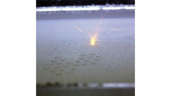
Related Content
3D Printed Titanium Replaces Aluminum for Unmanned Aircraft Wing Splice: The Cool Parts Show #72
Rapid Plasma Deposition produces the near-net-shape preform for a newly designed wing splice for remotely piloted aircraft from General Atomics. The Cool Parts Show visits Norsk Titanium, where this part is made.
Read More3D Printing Molds With Metal Paste: The Mantle Process Explained (Video)
Metal paste is the starting point for a process using 3D printing, CNC shaping and sintering to deliver precise H13 or P20 steel tooling for plastics injection molding. Peter Zelinski talks through the steps of the process in this video filmed with Mantle equipment.
Read MoreThis Year I Have Seen a Lot of AM for the Military — What Is Going On?
Audience members have similar questions. What is the Department of Defense’s interest in making hardware via 3D printing over conventional methods? Here are three manufacturing concerns that are particular to the military.
Read MorePostprocessing Steps and Costs for Metal 3D Printing
When your metal part is done 3D printing, you just pull it out of the machine and start using it, right? Not exactly.
Read MoreRead Next
3D Printed Polymer EOAT Increases Safety of Cobots
Contract manufacturer Anubis 3D applies polymer 3D printing processes to manufacture cobot tooling that is lightweight, smooth and safer for human interaction.
Read MoreAlquist 3D Looks Toward a Carbon-Sequestering Future with 3D Printed Infrastructure
The Colorado startup aims to reduce the carbon footprint of new buildings, homes and city infrastructure with robotic 3D printing and a specialized geopolymer material.
Read MoreBike Manufacturer Uses Additive Manufacturing to Create Lighter, More Complex, Customized Parts
Titanium bike frame manufacturer Hanglun Technology mixes precision casting with 3D printing to create bikes that offer increased speed and reduced turbulence during long-distance rides, offering a smoother, faster and more efficient cycling experience.
Read More
