Consider Thickness, Tolerance and Proximity in Laser-Sintered Holes
A study offers guidelines for hole design in laser sintering applications.
3D printing’s innate design capabilities allow holes to be incorporated directly into the part. But that doesn’t mean design engineers can just add holes to designs and call it a day. They first have to determine three key factors in hole design:
- Diameter versus thickness
- Diameter versus tolerance
- The hole’s proximity in regards to other part features
Thickness and Tolerance
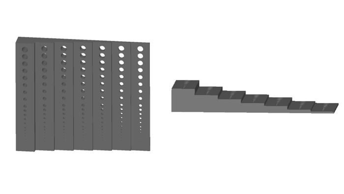
A survey led by the University of Texas at Austin with Stratasys Direct Manufacturing tested laser sintering (LS) techniques for the development of design guidelines, including hole formation. The research team designed a part with seven different wall thicknesses and 21 holes sintered into each thickness. The part was built in both a vertical and horizontal orientation. The goal of this test was to determine the design accuracy and hole resolvability in each orientation.
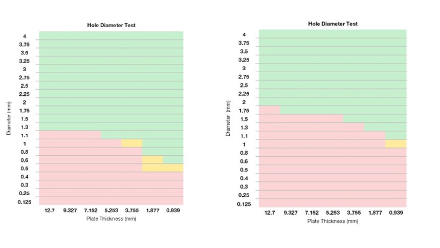
Hole diameter accuracy findings were based on a pass/fail basis. A pass meant the hole was fully resolved with light able to pass through, while a fail meant no light was able to pass through.
Based on the study’s findings, the following is recommended for hole diameter and wall thickness:
- Build holes with a diameter of at least 1.5 mm, as the project allows.
- For best resolvability chances, vertical orientation is better for holes smaller than 1.5 mm.
- Keep surrounding wall thickness at least 3.0 mm thick for better hole accuracy.
Proximity
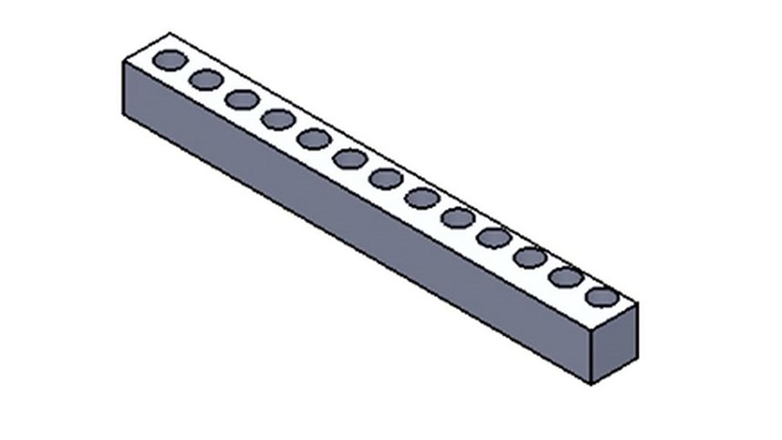
For hole proximity, the research team tested a square shaft with holes varying both in size and placement. The features within the part were built in either a horizontal or vertical orientation.
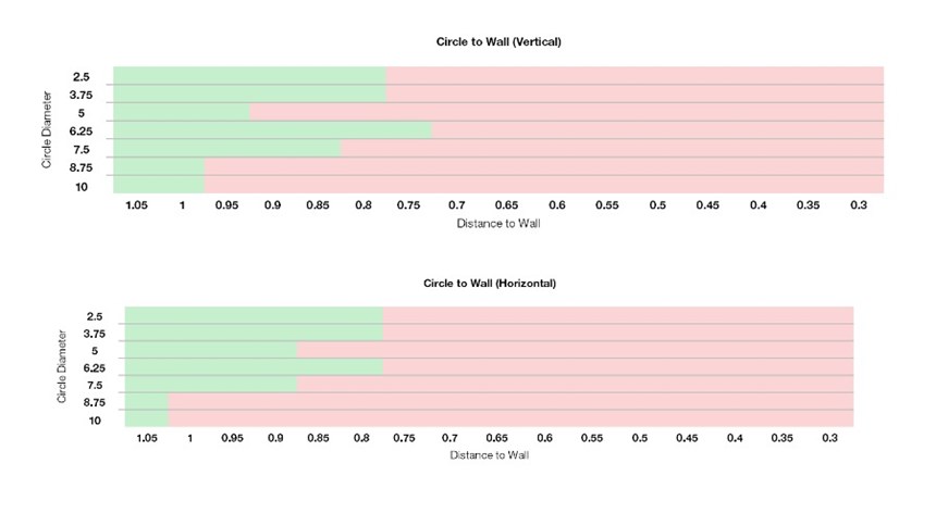
The hole accuracy and formation were tested similarly to the first part of the study; the hole either passed or failed with the exemption of a partial hole formation.
The study suggests the following recommendations for hole proximity:
- Design holes with a distance of no less than 0.8 mm to the closest feature, wall or part edge.
- Allow for more space between bigger holes and the closest feature, wall or part edge. Example: A hole diameter of 10 mm requires at least 1.05 mm distance from the nearest feature.
- Orient the hole features vertically. While there were minimal differences in hole resolvability between horizontal and vertical hole orientations, a vertical orientation will provide better wall support.
Related Content
-
Concept Sneaker Boasts One-Piece 3D Printed TPU Construction
The Reebok x Botter Concept Sneaker Engineered by HP premiered at Paris Fashion Week, hinting at manufacturing possibilities for the future of footwear.
-
Airless Basketball Shows Promise of 3D Printed Lattices: The Cool Parts Show Bonus
Successfully matching the performance of a standard basketball demonstrates the control possible over the mechanical properties of digital materials.
-
This Drone Bird with 3D Printed Parts Mimics a Peregrine Falcon: The Cool Parts Show #66
The Drone Bird Company has developed aircraft that mimic birds of prey to scare off problem birds. The drones feature 3D printed fuselages made by Parts on Demand from ALM materials.


