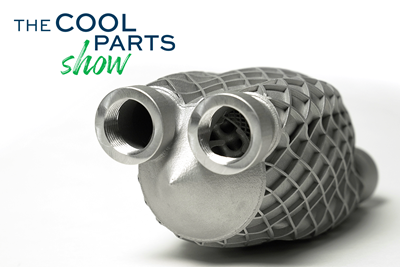
Preassembled Turbojet Engine, 3D Printed in One Build: The Cool Parts Show #75
Turbojet engines typically consist of hundreds or thousands of parts, but this engine — 2023 winner of The Cool Parts Showcase for Best Proof of Concept — was 3D printed as just two pieces, with the monolithic rotor embedded inside the stationary engine shell.
Share
Scroll to unlock this premium content if video does not play.
Gas turbine engines are typically complex machines, consisting of hundreds or thousands of parts that must be sourced and assembled. Technion Israel Institute of Technology, in collaboration with partners (including PTC, von Karman Institute for Fluid Dynamics and Izmir Katip Celebi University), undertook a project to see if a turbojet engine could instead be made from just two components, manufactured in one build through laser powder bed fusion (LPBF). The result is the engine seen in this episode, with a monolithic rotor and monolithic stationary shell both produced from Inconel 718 in a single build. While there are a few other elements required to make the engine functional, producing the bulk of its structure additively has potential benefits in terms of reducing engine cost, shortening supply chains, and even distributing or licensing production of similar gas turbine engines in the future. This preassembled turbojet engine was the 2023 winner for Best Proof-of-Concept Part in The Cool Parts Showcase. | This episode of The Cool Parts Show is sponsored by Carpenter Additive
The Cool Parts Show is a video series from Additive Manufacturing Media that explores the what, how and why of unusual 3D printed parts. Watch more here.
Have a cool part to share? Email us.
Related Resources
- Our episode on the Production category winner for The Cool Parts Showcase in 2023
- Our 2021 Proof-of-Concept winner, now a production part
- More on EOS, maker of the equipment used to produce this turbojet engine
- How 3D printing could advance just one component of a gas turbine: blades
- Another episode featuring a working motor embedded inside a fuel injector
- A workshop for metalworking facilities contemplating a move into metal AM using powder bed fusion
Transcript
Stephanie Hendrixson
We are back in the studio with another 2023 winner of The Cool Parts Showcase. This was our best proof-of-concept part. It is a preassembled turbojet engine printed in one build made up of just two pieces.
Pete Zelinski
Just two pieces. Except in this version, one of the pieces has been divided in half so you can see inside. There’s a lot of complexity here, because a conventional engine this size has a lot of separate components that all had to be fused together into this design of a one-build, one-material, two-piece turbojet engine.
Stephanie Hendrixson
This engine was developed at Technion - Israel Institute of Technology and it was sent to us by Beni Cukurel. Beni is the head of the Turbomachinery and Heat Transfer Laboratory inside of the Aerospace Engineering Department.
Beni Cukurel, Technion - Israel Institute of Technology
A gas turbine engine, as we call it, in principle is a very simple machine. So you have a compressor that compresses the flow where the pressure rises, and then we add heat to the flow in the combustor. And then we have a turbine that expands the flow. And, at different temperatures, the energy that’s required in order to compress and expand varies. Therefore, there is a residual abundance of energy at the exhaust. And this residual energy gets converted into kinetic energy in the nozzle, which is what we call thrust.
Pete Zelinski
So gas turbine engines are used in a lot of applications. They could be connected to a generator for power generation. Engines like this are used in aircraft. A small engine like this could be used in a small, remotely piloted aircraft.
Stephanie Hendrixson
And the reason this is so potentially powerful is, as we mentioned in the opening, turbomachinery tends to be complicated. It’s made up of a lot of different components. Those components are different materials produced by different suppliers. And somebody has to manage that whole supply chain, the sourcing and the assembly and all of that. And so getting to a preassembled design that could be made mostly in one build has a lot of advantages, not just for reducing the part count but also streamlining the workflow and the supply chain.
Pete Zelinski
So this is where it gets really fascinating. So all those different components, they’re not there for nothing. They’re all separate pieces, because each one of those pieces has been specified or refined or optimized to perform its role in the overall system as well as possible. And the result of that is an optimally performing engine. But there is cost to that. The accumulation of all of those different, precisely carefully chosen components is the expense of all those different suppliers for all those different components and all of the assembly that’s involved.
So what if you flip that around? What if you impose a lot of constraint? What if you say this whole engine, it’s going to be made out of just one material and it’s not going to be optimized for the ideal possible performance, but instead, what if we design with the aim of simplicity? How simple and how cheap is it possible for an engine like this to be?
Beni Cukurel
Well essentially, through design iterations, we managed to fuse all of the rotating parts into one subassembly and all of the stationary parts into one subassembly. On the rotating side, the monolithic rotor consists of the turbine at the bottom and, as you are going up, you see the bearing journal and then there’s a compressor. Whereas, surrounding it you have the stationary section that consists of the heat exchanger, nozzle guide veins, the combustor and the bearing housing, the diffuser and the intake. The novel thing, this whole approach, was to be able to create self-supported two parts that coexist, literally one inside the other, while not interfering with the function of one another.
Stephanie Hendrixson
I want to reiterate that it was not an accident that they ended up with just two parts. This was the intention from the very beginning. It was not the case that they designed all these individual components and then figured out a way of mushing them all together. They really set out from the get-go to come up with a design that would be as few components as possible, ideally just two.
Beni Cukurel
What we did is a system-level, support-free design perspective for additive manufacturing that inherently incorporates all the stationary and moving parts, and how they can be created in a self-supported way. And this was actually one of the main challenges. It would be impossible — or nearly impossible — to be able to come from a complex engine design and reduce the part count by fusing different parts and end up with such an architecture.
Pete Zelinski
Technion - Israel Institute of Technology — so this institute gets referred to as Israel’s MIT. A lot of math and science and engineering talent, a lot of access to and connection to that kind of talent. And the team developing this engine drew on those resources, drew on that network for help in consolidating all these different components into these solid forms.
Beni Cukurel
We are, in essence, in the lab, human machinery people. So we actually started the approach from reduced order modeling of aerodynamics. We created tools in Matlab that define each one of the components and how to be able to actually create them in a self-supported way. In the following, we did some fluid simulations in Ansys. And, at that point, we actually started a partnership with the von Karman Institute for Fluid Dynamics in Belgium and İzmir Kâtip Çelebi University in Turkey in order to be able to put together an engine that actually took the form that you have all seen.
So, while this was taking place, this was mostly a challenge of turbomachinery. We started also to encounter issues with the CAD design as well. And, as you can see, the architecture is quite complex. So this is why we partnered up with PTC and utilized the Creo tools in order to be able to define the topology. So, once the topology was defined, we checked for printability in Materialise Magics by slicing the different components. We did some process simulation in Simufact Additive from Hexagon and we started printing samples.
Once we printed samples, we scan them. We have a Zeiss scanner here in the lab. And we conducted in Simufact Additive this pre distortion calibration that’s required in order to get the architecture that we desired. At last, the parts were printed in the EOS M 290 and M 300 printers at multiple locations.
Stephanie Hendrixson
So printed in multiple locations because Technion was printing in Israel and EOS was also printing in North America. But, in both cases, the turbojet engine was made entirely from Inconel 718 through laser powder bed fusion. There’s some minimal postprocessing that happens after printing, so depowdering and heat treat. But the 3D printing really is the bulk of the production process. And so it’s really important in that process to achieve the complex interior of this outer shell, and also to ensure that this rotor is going to be able to turn — to rotate — almost immediately out of the printer.
It was really critical to maintain a gap between the two parts, because if somehow they got fused together during the printing process — again this rotor is going to be enclosed inside of the shell — it would be difficult, if not completely impossible, to separate them after the fact.
Beni Cukurel
To be able to create this gap between the rotor and the stationary housing is one of the most challenging parts of the process. Because the moment that you actually let go of your bearings, now you need to rely on the fluidic pressure — in this case, the fuel — in order to be able to stabilize the rotor inside the housing.
There were multiple approaches, in order to be able to facilitate this. One of them was the design itself. So we wanted to make sure that the design would be self-supported on the rotor and the stationary components around it. And that’s essentially what creates the journal bearing. But, beyond this, we had to incorporate a lot of process simulation in order to make sure that the two parts wouldn’t bend toward one another, and we would be able to retain the small gaps that are required.
At the end of the multiple processes, we ended up with a gap of around 200 microns, which I would consider a success from the perspective of manufacturing technology. But, from the perspective of fluidic bearing performance, this is a big challenge still. And this is still one of the things that we are working on actively in order to be able to improve the bearing performance.
Pete Zelinski
The engine is printed in two different pieces. But another way to think about that is the engine is printed. All of the rotating components are printed into this spinning portion. All the stationary components are printed into this stationary portion. And yeah, between them there’s that gap. Beni described that. The gap is there because that is where that hydrostatic bearing has to operate. And maintaining just the right precision of that gap during 3D printing, for the sake of that hydrostatic bearing, that was one of the challenges the team faced.
The team succeeded at meeting that challenge. And one effect, one payoff, is that in producing that engine, the team revealed just how much of the cost of an engine like this is due to assembly.
Beni Cukurel
The cheapest engine of this thrust class basically sold for somewhere around $50,000 to $75,000. So whereas this engine, the manufacturing cost comes down to depreciation of the printer as well as the powder. So we are now talking about a cost of anywhere between $10,000 to $15,000 in terms of manufacturing cost.
There’s an additional fringe benefit which would, I think, fulfill my vision. If, instead of engine manufacturers creating engines, what if the platform manufacturers would be able to just license out to design and print their own engines on demand? So this would be actually a really a disruptive change in the way that the entire gas turbine market is operating today.
Stephanie Hendrixson
So this whole idea of 3D printing a preassembled engine, it’s not just an interesting engineering exercise. There are some real potential cost savings like Beni just outlined. There are also the benefits of maybe being able to move or distribute production like Technion and EOS already kind of demonstrated.
There are also opportunities to maybe reduce the workforce requirements, instead of that full supply chain of all those different manufacturers, all those different people involved. If you have one engineer and one printer making this design, you’re producing the bulk of the engine in just one operation.
All right, let’s recap.
Pete Zelinski
3D printed turbojet engine. All of the rotating elements consolidated into one rotating piece. All of the stationary elements consolidated into one stationary piece. Two-piece 3D printed engine.
Stephanie Hendrixson
This is very different from how turbomachinery is typically made being assembled from lots of different components. By consolidating the assembly into just the rotating and stationary components, they’re simplifying the supply chain, simplifying streamlining the workflow and also introducing the possibility of distributed manufacturing, maybe even licensing engines like this to manufacturers.
So the version of this engine that won The Cool Parts Showcase in the category in 2023 was all about just demonstrating that it’s possible to produce a preassembled turbojet engine that will operate like an engine. They were successful in doing that, and this application has advanced since then. Now it’s all about iterating and improving on what they’ve already demonstrated.
Related Content
Spherene Creates Metamaterial with Geometry Derived from Spheres
An algorithm developed by Spherene Inc. generates Adaptive Density Minimal Surfaces (ADMS) as a self-supporting infill strategy that can be used to reduce mass and manage material properties in 3D printed parts.
Read MoreVixiv Developing AI Alternative to Generative Design
Newly opened Ohio facility is where geometric cells are made and tested to inform the machine learning system that will “know,” without computation, what 3D printed form satisfies a given set of needs.
Read MoreThis 3D Printed Part Makes IndyCar Racing Safer: The Cool Parts Show #67
The top frame is a newer addition to Indycar vehicles, but one that has dramatically improved the safety of the sport. We look at the original component and its next generation in this episode of The Cool Parts Show.
Read More3MF File Format for Additive Manufacturing: More Than Geometry
The file format offers a less data-intensive way of recording part geometry, as well as details about build preparation, material, process and more.
Read MoreRead Next
Variable Resistance Valve Trim Achieves Lead Time Reduction Through AM: The Cool Parts Show #69
Baker Hughes is realizing shorter lead times and simplified manufacturing through powder bed fusion to produce valve trims previously assembled from many machined metal parts.
Read MoreBeehive Industries Is Going Big on Small-Scale Engines Made Through Additive Manufacturing
Backed by decades of experience in both aviation and additive, the company is now laser-focused on a single goal: developing, proving and scaling production of engines providing 5,000 lbs of thrust or less.
Read More3D Printed Heat Exchanger Uses Gyroids for Better Cooling | The Cool Parts Show #43
Replacement heat exchanger for a helicopter is half the size and delivers 4× the cooling, thanks to a geometry that could only be made via additive manufacturing.
Read More
.jpg;width=70;height=70;mode=crop)


